

Inspecting a commercial fire sprinkler system’s signs, gauges, and alarms
QRFS has taken a close look at the inspection needed for various components of a fire sprinkler system in this series:
Part one: The annual visual inspection of sprinkler heads
Part two: The annual visual inspection of pipe and fittings
Part three: The inspection requirements for fire pumps
In this fourth installment, we take a look at the basic inspections needed for other components, including gauges, alarms, and signage.
Are you just looking to buy parts? Jump to the search function at the top of the page, or see our large inventory of all things fire sprinkler.
Nonworking alarms are cause for alarm
NFPA stipulates that all alarms are checked on every three months to make sure they aren’t obviously damaged:
From the 2017 Edition of NFPA 25
5.2.4 Waterflow Alarm and Supervisory Signal Initiating Device. Waterflow alarm and supervisory signal initiating devices shall be inspected quarterly to verify that they are free of physical damage.
The waterflow alarm, of course, sounds when it detects the movement of water, such as during sprinkler deployment or testing. They can be mechanical, vane-type, paddle-type, or pressure switch-type; all need to be checked for damage every three months. But what classifies as a supervisory signal initiating device?
Numerous things. NFPA explicitly defines supervision as “a means of monitoring system status and indicating abnormal conditions,” and a supervisory signaling device is “designed to transmit a warning of something that may affect the operation of a fire suppression system.” Examples include:
- An anti-tamper switch that ensures a control valve remains open; if control valves are closed, the sprinkler system will not deploy in an emergency.
- A low-water alarm in a water storage tank.
- A low-temperature alarm (at various points) that indicates freezing conditions.
- An alarm indicating loss of power to a fire pump or other piece of equipment.
Take a full inventory of all supervisory signaling devices to ensure that they are checked and free of damage every quarter.

A hydraulic system information sign. You can purchase one here.
Sprinkler signage inspection required by NFPA
You’ve got to make sure all necessary signs are in place and in the right format on an annual basis, plus verify that all pertinent information is included in them:
Hydraulic design or pipe schedule sign
From the 2017 Edition of NFPA 25
5.2.5* Hydraulic Design Information Sign. The hydraulic design information sign shall be inspected annually to verify that it is provided, attached securely to the sprinkler riser, and is legible.
A.5.2.5 The hydraulic design information sign should be secured to the riser with durable wire, chain, or equivalent.
5.2.5.1 A hydraulic design information sign that is missing or illegible shall be replaced.
5.2.5.2 A pipe schedule system shall have a hydraulic design information sign that reads “Pipe Schedule System.”
There are two essential methods of designing a fire sprinkler system: hydraulic and pipe schedule. Hydraulic systems calculate pressure, internal friction of the pipe, and other “fundamental laws of hydraulics” to flexibly design a sprinkler system with the intended coverage area. Pipe schedule accounts for the occupancy of a building and “specifies the number of sprinklers that can be supplied by a given pipe size.”
NFPA now requires that all new installs use hydraulic calculations, so pipe schedule systems are becoming less common – they are “typically found in buildings built before the 1970’s.” Nevertheless, if you have one, make sure it’s marked as such – and if you have a more common hydraulic system, make sure the sign is present, in the right format, appropriately secured to the riser, and that it has all of the right information fill in. Below is an example of a hydraulic information sign and the information required:

General information sign
The main purpose of the general information sign is “to provide vital information that might not otherwise be readily known to anyone maintaining a system.”
From the 2017 Edition of NFPA 25
5.2.7 Information Sign. The information sign required by 4.1.9 shall be inspected annually to verify that it is provided, securely attached, and legible.
5.2.8* General Information Sign. The general information sign required by NFPA 13 shall be inspected annually to verify that it is provided, securely attached, and legible.
A.5.2.8 The information sign should be secured with wire, chain, or equivalent to each system control valve, antifreeze loop, and auxiliary system control valve indicating the information required by 4.1.9.
4.1.8 Valve Location. The location of shutoff valves shall be identified at the system riser or other approved locations.
4.1.9.1 A permanently marked metal or rigid plastic information sign shall be placed at the system control riser supplying an antifreeze loop, dry system, preaction system, or auxiliary system control valve.
4.1.9.2 Each sign shall be secured with a corrosion-resistant wire, chain, or other approved means and shall indicate at least the following information:
(1) Location of the area served by the system
(2) Location of auxiliary drains and low-point drains for dry pipe and preaction systems
(3) The presence and location of antifreeze or other auxiliary systems
(4) The presence and location(s) of heat tape
Having a map to the location of shutoff valves is pretty handy in the event of an accidental sprinkler discharge or a burst pipe – and having this clearly-marked information could save a lot of water damage.
NFPA states that the general information “sign is particularly useful in addressing freeze threats by identifying any locations with heat tape and acknowledging that auxiliary and low-point drains are installed on the system along with their number and location. If this information is not known, the system can be damaged due to freezing of water in the trapped sections of pipe.”
The term “heat tape” actually refers to “heat tracing,” also known as “heating cable, heat tracing cable, or heater cable,” which is a method of running an electrical heating element around pipe that is subject to freezing. NFPA 25 requires an inspection of heat tracing:
5.2.6 Heat Tracing. Heat tracing shall be inspected and maintained in accordance with manufacturer’s requirements.
Notice that there is no interval specified; this is likely because NFPA instructs to default to the manufacturer’s recommended schedule. That said, NFPA indicates that this inspection should be done annually on its sample “Inspection, Testing, and Maintenance” form for wet sprinkler systems.

When maintenance professionals or inspectors know where all of these items are found, they can more easily ensure that all of them are working properly. If you don’t have all of the information for the general info sign, consult the design drawings of the system, the contractor who installed it, or engage a fire safety professional to map the components of the system.
And speaking of preventing freeze damage …
Antifreeze information sign
From the 2017 Edition of NFPA 25
5.2.9 Antifreeze Information Sign. The antifreeze information sign required by 4.1.10 shall be inspected annually to verify that it is present, securely attached, and legible.
4.1.10 Antifreeze Information Sign. An antifreeze information sign shall be placed on the antifreeze system main valve, which indicates the manufacture type and brand of the antifreeze solution, the concentration by volume of the antifreeze solution used, and the volume of the antifreeze solution used in the system.
This sign has taken on great importance in the past decade. After a series of incidents in which antifreeze solutions actually ignited and injured people when sprinklers deployed, NFPA has limited their use to certain maximum concentrations and systems installed prior to Sept. 30, 2012 – and plans to phase out the use of current antifreeze solutions entirely by 2022. Thus, the information on this sign is vital to ensure that the antifreeze doesn’t present a hazard.
For an in-depth look at the antifreeze issue, check out our blog: “The Use of Antifreeze in Fire Protection Systems.”
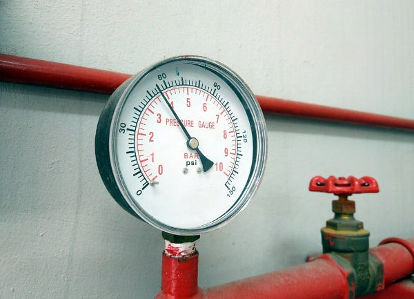
Gauge inspection required by NFPA
Part one and part two of this series, as well as the section above, have covered all of the inspections that are specifically required of fire sprinkler systems. There are other needed inspections of components that can apply to any fire protection system, however, including a fire sprinkler system. This includes gauges:
From the 2017 Edition of NFPA 25
13.2.7.1.1* Gauges shall be inspected monthly to verify that the gauge is operable and not physically damaged.
13.2.7.1.2 Gauges monitoring water pressure shall be inspected quarterly to verify that normal water supply pressure is being maintained.
13.2.7.1.3 Gauges monitoring air or nitrogen pressure shall be inspected monthly to verify that normal air or nitrogen pressure are being maintained.
13.2.7.1.3.1 The gauge on the quick-opening device, if provided, shall indicate the same pressure as the gauge on the system side of the dry pipe valve.
13.2.7.1.3.2 Where air pressure supervision is connected to a constantly attended location, gauges shall be inspected quarterly.
13.2.7.1.4* For dry pipe or preaction systems protecting freezers with an air pressure gauge(s) on the air line(s) between the compressor and the dry pipe or preaction valve, the air pressure gauge near the compressor shall be compared monthly to the pressure gauge above the dry pipe or preaction valve.
13.2.7.1.4.1 When the gauge near the compressor is reading higher than the gauge near the dry pipe valve, the air line in service shall be taken out of service and the alternate air line shall be opened to equalize the pressure.
13.2.7.1.4.2 An air line taken out of service in accordance with 13.2.7.1.4.1 shall be internally inspected, removed of all ice blockage, and reassembled for use as a future alternate air line.
Gauges are obviously a critical component of fire sprinklers, as their readings indicate whether the system has adequate pressure to do its job. Wet systems use a water pressure gauge, whereas dry systems use gauges that monitor the gas pressure. What is considered “normal water supply pressure” can vary, but should essentially be established by system design requirements, past inspections, and any special conditions, often based on the determination of a life safety professional.
Inspectors must also ensure gauges are not damaged, readable, listed for use in its present application (via a manufacturer’s code shown on the gauge), and that it has been tested sometime within the past five years. Check out these from the Fire Protection Deficiencies blog, which is a great resource for seeing what not to do on a fire protection system:


To be continued: What Facility Managers Need to Inspect on a Fire Sprinkler System
This concludes part four of QRFS’ series on the inspection of commercial fire sprinkler systems – but there is more to come. In the next piece, we’ll detail the inspection requirements of valves and other common components.
If you need to buy items for a commercial fire sprinkler system, review our escutcheons, cover plates, commercial fire sprinkler heads, and other components and tools, or just use the search function at the top of the page.
If you have any questions regarding commercial fire sprinklers or need help finding something, give us a call at 888.361.6662, comment below, or fill out our contact form.
What would be a pressure change that would cause concern? Our gauge is only 2 psi different from last month, but the outside temps and barometric pressures have changed a lot, which could be the reason for the change.
Ross — section 13.2.7.3 of NFPA 25 requires that gauge display readings have no more than a 3% error in either direction:
“13.2.7.3 Gauges not accurate to within 3 percent of the full scale shall be recalibrated or replaced.”
So, it depends on the full scale of your gauge. For example, if it’s a 0 to 300 PSI scale, there’s 9 PSI to work with.
If there is a trouble on an alarm panel, can you pass or complete a quarterly sprinkler system test?
Robert — We’re not 100% on what you’re referencing in the mention of a “quarterly sprinkler system test.” For example, the blog above is referencing inspections (not tests), including a quarterly NFPA 25 inspection of waterflow alarms and supervisory signal devices to ensure they aren’t physically damaged. Mechanical waterflow alarms, for example, are tested quarterly to ensure they sound properly, but their function isn’t necessarily dependent on being networked to an alarm panel. Valve supervisory devices are tested semiannually (according to NFPA 25 rules) and are often networked to a control panel.
So, the best answer we can provide is “it depends,” and your best option is to consult with a local fire protection pro who can assess your specific system—especially if you have a trouble signal!
If the gauge is working properly is there any requirement to replace a gauge after “x” number of years?
Paul — Gauges must be tested every five years and recalibrated or replaced if necessary (some people just replace them instead of testing their accuracy). Here are the relevant passages from NFPA 25 (2023 edition):