


Best practices for installing dry pipe valves, check valves, and quick-opening and antiflooding devices
Dry sprinkler systems are essential for reliably protecting properties (or parts of them) exposed to freezing temperatures from fires. But the additional components they require compared to traditional wet sprinkler systems present unique installation challenges and considerations.
In the last installment of our series on dry sprinkler systems, we delivered an overview of National Fire Protection Association (NFPA) requirements for installing dry sprinklers properly, from choosing the best pipes to managing cold conduction. In this post, we dig deeper into NFPA rules for installing dry sprinkler parts, including dry pipe valves, check valves, and quick-opening and antiflooding devices.
Previous installments in the series:
A Guide to Dry Sprinkler Systems, Part 1: System Overview
A Guide to Dry Sprinkler Systems, Part 2: Components and Installation Requirements
Are you looking to buy parts for your building’s sprinkler system? QRFS offers a range of dry sprinkler heads available on special order. Call us at 888.361.6662 or email support@qrfs.com.
You can also view our in-stock selection of sprinkler gauges, valves, switches, and components.
Extra parts make installation of dry systems more complex
NFPA stipulates using dry sprinkler systems when the ambient temperature of an area can’t be maintained at or above 40°F (4°C), putting wet systems at risk of breaks and malfunctions due to freezing.
The more complex operation of a dry sprinkler system requires extra control equipment and air pressurization devices not found in wet systems. NFPA 13: Standard for the Installation of Sprinkler Systems sets strict guidelines for a dry system’s component options to protect people and property from fires. Let’s take a look at some unique components of a dry sprinkler system and NFPA’s detailed installation requirements for each.
Protecting the dry valve from freezing
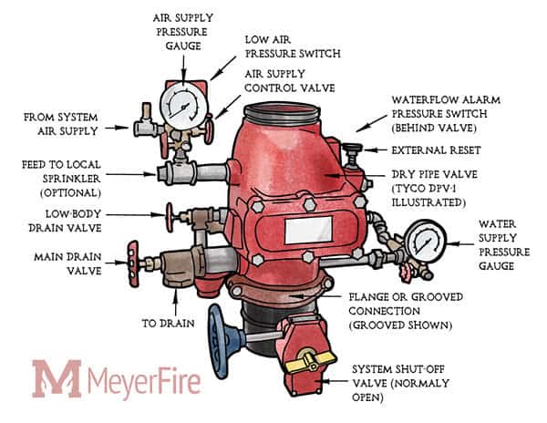
The dry valve, or “dry pipe valve,” is the heart of a dry sprinkler system. Installed at the sprinkler riser, it stands as the sentry that keeps the water supply from entering the pipes until a fire causes one or more sprinklers to operate.
Dry valves generally operate on a differential principle: for instance, if a valve has a 6:1 differential, it only requires 1 psi of air pressure to hold back 6 psi of water pressure. When the air in the pipe network escapes through an open sprinkler, the water pressure below the valve becomes greater than the air pressure above it, pushing the dry valve’s clapper open and releasing water into the pipes.
The clapper serves as the interface between the air (or nitrogen gas) and water on a dry valve. Its surface area is disproportionately larger on the air side than the water side, enabling the gas to be kept at a relatively low pressure while still holding the clapper closed.
Incidentally, when it’s possible to reseat the dry valve after it’s tripped without draining the sprinkler system, NFPA 13 requires an automatic high-water level signaling device or automatic drain to be installed. These devices prevent water from accumulating above the clapper and causing damage.
From the 2022 Edition of NFPA 13
8.2.5.4.2 Differential Dry Pipe Valve. Protection against accumulation of water above the clapper shall be provided for differential dry pipe valves in accordance with 8.2.5.4.3.
8.2.5.4.3 High Water Level Device. An automatic high water level signaling device or an automatic drain shall be permitted.
Different dry valves can have different differentials, so it’s critical to review your manufacturer’s technical data to determine the air pressure a system requires based on the pressure of the water supply. Once you know the differential, you can divide the water supply pressure by the water differential number (in our example above, it was 6) to determine the amount of air pressure needed to avoid accidental discharges — adding 15 or 20 psi to be safe.
8.2.6.7.1 The system air pressure shall be maintained in accordance with the instruction sheet furnished with the dry pipe valve, or shall be 20 psi (1.4 bar) in excess of the calculated trip pressure of the dry pipe valve, based on the highest normal water pressure of the system supply.
Since the reliable operation of the dry valve is critical to dry sprinkler performance, NFPA 13 sets strict requirements designed to protect the valve from freezing. It also requires the valve to be located as close to the overhead sprinkler piping as possible to ensure that flame-retarding water reaches activated sprinklers within 60 seconds (and less in other systems/scenarios).
To achieve these mandates, NFPA 13 recommends the construction of a heated “valve room or enclosure of adequate size” around the valve and water supply piping (A.8.2.5).
The “valve room” should be lighted and have a permanent heat source. For the most part, heat tape can’t be used instead of heated valve enclosures to protect the valve and its supply pipe from freezing. In the appendix section A.8.2.5.1, however, NFPA 13 acknowledges that “the occasional exposure of valves to short exposures of air temperatures below 40°F (4°C) that would not cause the valves to freeze does not justify the construction of a valve room.”
8.2.5* Location and Protection of Dry Pipe Valve.
8.2.5.1* General. The dry pipe valve and supply pipe shall be protected against freezing and mechanical injury.
8.2.5.2 Valve Rooms.
8.2.5.2.1 Valve rooms shall be lighted and heated.
8.2.5.2.2 The source of heat shall be of a permanently installed type.
8.2.5.2.3 Heat tape shall not be used in lieu of heated valve enclosures to protect the dry pipe valve and supply pipe against freezing.
More NFPA requirements for dry sprinkler parts
NFPA 13 also sets specific standards for the installation of several other dry sprinkler components:
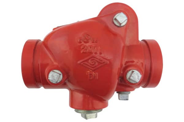
Check valve
Check valves are used in sprinkler systems to prevent the backward flow of water. NFPA 13 only allows employing them for subdividing dry systems when they are installed in heated environments (8.2.3.9). When they are used, section 8.2.3.9.1 calls for installers to drill a hole with a diameter of 1/8 in. (3mm) into the clapper of each check valve to permit equalization of air pressure throughout the system.
In order to drain the system, NFPA 13 also requires installers to connect an approved indicating drain valve to each check valve if auxiliary drains are not provided for the subdivided sections.
8.2.3.9.2 Where auxiliary drains are not provided for each subdivided section, an approved indicating drain valve supervised in the closed position in accordance with 16.9.3.3, connected to a bypass around each check valve, shall be provided as a means for draining the system.
Quick-opening device (QOD)
NFPA 13 permits the use of listed QODs in dry sprinkler systems to speed the operation of the dry valve and accelerate water delivery times to meet minimum speed requirements. Listed QODs, tested and certified to UL 1486, must be installed “as close as practical” to the dry valve (8.2.4.2).
There are two main types of QODs. The most common are accelerators, which quickly sense rapid air pressure drops and push pressurized air into the dry valve to upset its differential faster. In contrast, exhausters discharge large amounts of pressurized air directly into the atmosphere instead of waiting for it to escape through the sprinkler.
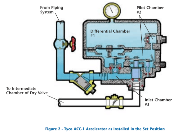
The use of accelerators is significantly more common than exhausters, and there are two types of the former: mechanical accelerators and electronic accelerators. Mechanical accelerators use “restricted orifices and many moving parts intended to detect a small pressure imbalance” but these “fine tuned devices … require frequent maintenance to function properly.” The electronic versions have been introduced to make them more reliable and easier to maintain.
Installers must follow these NFPA 13 guidelines:
8.2.4.3 To protect the restriction orifice and other operating parts of the quick-opening device against submergence, the connection to the riser shall be above the point at which water (priming water and back drainage) is expected when the dry pipe valve and quick-opening device are set, except where design features of the particular quick-opening device make these requirements unnecessary.
8.2.4.4 Where a valve is installed in the connection between a dry pipe sprinkler riser and a quick-opening device, it shall be an indicating-type valve that is sealed, locked, or electrically supervised in the open position.
8.2.4.5 A check valve shall be installed between the quick-opening device and the intermediate chamber of the dry pipe valve, where the quick-opening device requires protection against submergence after system operation.
8.2.4.6 If the quick-opening device requires pressure feedback from the intermediate chamber, a valve type that will clearly indicate whether it is opened or closed shall be permitted in place of that check valve.
8.2.4.7 Where a valve is utilized in accordance with 8.2.4.6, the valve shall be constructed so that it can be locked or sealed in the open position.
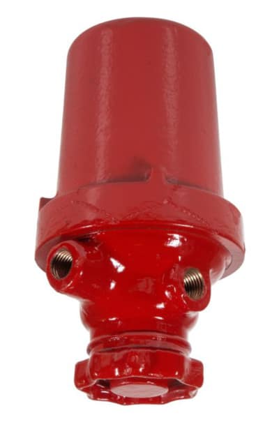
Antiflooding device
UL-listed antiflooding devices installed with accelerators initially help keep a dry sprinkler system’s pneumatic pressure from opening the dry valve until fire conditions are present. Once the dry valve trips, the antiflooding device also stops the water flooding the system from entering the accelerator and clogging its restricted orifices with foreign objects. It should be installed as follows:
Section 8.2.4.8 of NFPA 13 requires a listed antiflooding device to “be installed in the connection between the dry pipe sprinkler riser and the quick-opening device” unless the quick-opening device “is listed or approved without […] an antiflooding device” or “has built-in antiflooding design features.”
To be continued: An overview of dry system components and installation requirements
Dry fire sprinkler systems are comprised of many complex parts. Taking the time to understand NFPA requirements and installing them properly will ensure that a system offers reliable automatic fire protection when temperatures drop.
Check out the next installment in this series: Guide to Dry Sprinkler Systems, Part 4: Installation of Air-Compressors and Air Maintenance Devices.
If you’re looking to buy components for your dry pipe sprinkler system, QRFS offers a range of dry sprinkler heads available on special order. Simply give us a call at 888.361.6662 or email support@qrfs.com and we’d be happy to help.
We also stock sprinkler gauges, valves, switches, and components that are applicable in dry systems.
This blog was originally posted at blog.qrfs.com. If this article helped you, check us out at Facebook.com/QuickResponseFireSupply or on Twitter @QuickResponseFS.