

Standards guiding the manufacturing of angle valves create cross-compatibility across industries, but careful selection is warranted
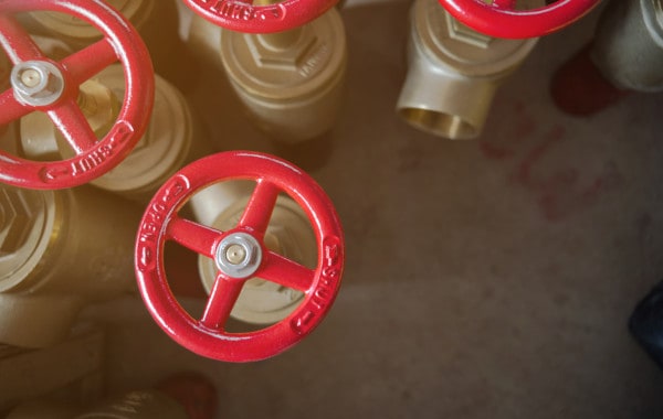
All valves have a mechanism used to start, stop, and sometimes restrict the flow of material through pipes. Many are marketed for purposes ranging from refrigeration to fire protection, raising the question: what really matters in a valve?
In this article, we answer that question by taking a close look at angle valves, discussing their construction, manufacturing standards, and suitability for a variety of applications. We also specifically examine angle valves for fire protection, explaining how they differ from general-purpose valves and why.
Already familiar with the subject? Feel free to view our angle valves for trim and drain applications or our hose angle valves for standpipe and other fire protection systems.
Angle valves typically control flows with a disk, making them useful for throttling applications and more
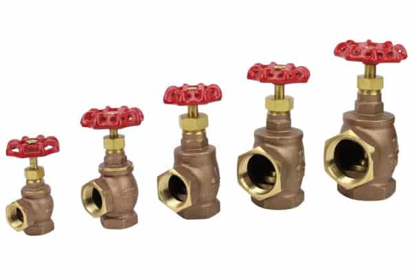
Angle valves combine the functionality of a pipe elbow and a valve into a single device. Most are simply “angle-pattern globe valves.” Originally named for their rounded body, these globe valves impede or permit water’s movement by moving a plug or disc into the path of flow.
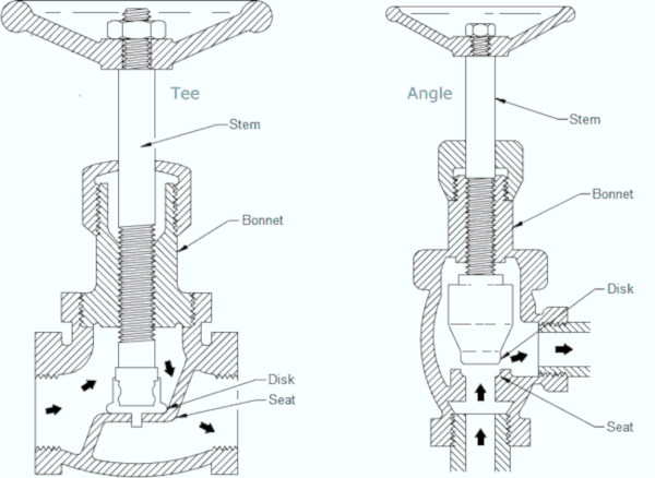
As a type of globe valve, angle valves are often recommended for throttling applications where it’s not uncommon to restrict the flow of water. Other valves perform well when fully open or fully closed, but lack the precision needed to effectively control water at a reduced rate. Some ball valves, for example, flow only 10% of their capacity when more than a third of the way open, and flow only 30% of their capacity when nearly two-thirds open. Gate valves, another common type, are also better-suited to full or no flow.
One disadvantage of angle valves is that forcing water to move through them at an angle reduces pressure. But, as an alternative to installing a traditional T-pattern globe valve with an elbow, angle valves cause a smaller drop in pressure and less resistance to flow. They also reduce the number of fittings installers need, reducing labor costs.
Various ratings allow designers and installers to quickly evaluate angle valve characteristics
Valves are sometimes classified using guidelines from the American Society of Mechanical Engineers (ASME), an organization that serves engineers and scientists, in part, through the development of manufacturing standards. Manufacturers describe their valves’ specifications—designated by the word “Class” and a three-or-four-digit number—using ASME’s standards. More often than not, these classes are referred to as “ANSI Class” ratings, a phrase that hearkens back to some standards’ history with the American National Standards Institute (ANSI).
ASME B16.34 establishes numerous pressure classes for flanged, threaded, welding-end, and other valves. These classes are used to determine the maximum allowable working pressures for valves at given temperatures. All working components of an ASME-compliant valve—from the body to the trim components and inserts—are suitable for use at these listed temperatures and pressures.
Besides ASME, one other organization is commonly referenced when describing angle valves: the Manufacturers Standardization Society of the Valves and Fittings Industry, or MSS. Like ASME, MSS provides guidelines for valve construction by type and construction. MSS SP-80, for example, provides requirements specific to brass valves used for general-purpose services. Valves made from gray iron, including angle valves, follow standards in MSS SP-85. These standards govern the materials, dimensions, and other characteristics of this equipment when it’s operating at a select temperature and pressure.
Valves that don’t reference ASME’s standards typically provide one or more working pressure ratings at specified temperatures. We’ve covered the most common types in our write-up on fire safety valve pressure ratings.
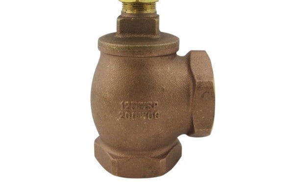
Two leading ratings—both defined by MSS—are Steam Working Pressure (SWP) and Cold Working Pressure (CWP). SWP indicates the valve’s maximum working pressure at temperatures at or above 330 F (166 C), and Cold Working Pressure (CWP) provides the valve’s pressure rating at ambient temperatures between -20 F (-29 C) and 100 F (38 C). Although many such valves may meet some of ASME’s standards—and may even feature many of the same components—others utilize parts that lower working pressures or rule out the valve’s use at certain temperatures.
Class 125 and Class 150 angle valves are suited to a wide range of water and steam applications, but some differences impact their suitability
For many purchasers, valves in two ASME or ANSI classes will do the job: Class 125 or Class 150. While their pressure-temperature ratings are among some of the lowest described by ASME, they’re still more than enough in many applications.
For example, Class 150 bronze valves made to the standards of MSS SP-80 are rated for 200 PSI at temperatures between -20 and 150 degrees Fahrenheit (-29 to 66 C). These same valves can withstand pressures of 125 PSI at 406 degrees Fahrenheit (208 C). Threaded Class 150 valves made from brass have slightly higher pressure-temperature ratings, making them suitable for use at pressures up to 300 PSI within normal operating temperatures and 150 PSI at 406 degrees Fahrenheit (208 C).
These ratings make Class 125 and 150 angle valves a popular choice with condensers, chilled water, hot water heating service, and low-pressure steam service. Class 125 valves cover most of this ground, although Class 150 valves will be needed for steam service when operating pressures approach 150 PSI. For medium-pressure steam service, where pressures are between 15 and 125 PSI, Class 125 valves may be used.
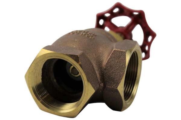
Still, some distinctions can be made between valves conforming to these standards. For hot water service, valves with synthetic or coated handles can protect users against heat. In irrigation service, angle valves for underground use often feature cross-type operating handles designed to engage with sprinkler valve keys. And in potable water service, angle valves should comply with the Safe Water Drinking Act (SDWA). With some exceptions, the SWDA requires pipe, fittings, and fixtures in residential and non-residential facilities providing water for human consumption to be “lead-free,” restricting lead content to a weighted average of 0.25% or less across their wetted surfaces. In some states, these lead-free valves require third-party certification, a service often provided by NSF international.
Two angle valve types feature prominently in fire protection
In fire sprinkler and standpipe systems, many angle valves act as trim valves. These items play a supporting role, contributing to the proper function of these systems without directly controlling the flow of water to sprinkler heads or other critical components.
As we’ve covered in our guide to trim valves, the National Fire Protection Association (NFPA) has little information specific to trim valves. Unlike other valve types, they don’t require third-party listings under NFPA standards.
Retailers and manufacturers of fire sprinkler trim valves may make little to no mention of ASME classes or MSS standards. Instead, these valves are typically designed to have cold working pressures suitable for the systems they serve (typically, 175 PSI). Often, these valves serve as part of a main drain assembly at a fire sprinkler system riser. While they don’t require listings in systems compliant with NFPA 13: Standard for the Installation of Sprinkler Systems, trim and drain valves may be listed in accordance with UL 258.
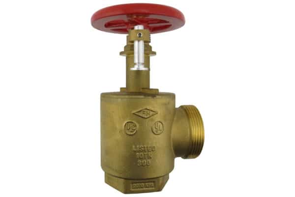
One other type of angle valve for fire protection—the fire hose angle valve—is used with rack hose assemblies or as a fire department outlet connection, providing a building’s occupants or firefighters with convenient access to water from a standpipe system. Most feature inlets threaded with National Pipe Thread (NPT) for connection to system piping. Their outlets typically connect to female swivels on fire hoses, which means that they typically use either male National Standard Thread (NST) or National Pipe Straight Hose Thread (NPSH).
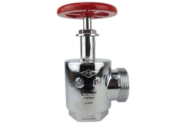
Fire hose angle valves belong to one of two types: standard valves or pressure-restricting valves. Standard fire hose angle valves allow for complete control over opening and closure and can deliver water at their maximum pressure. Pressure-restricting hose angle valves use an adjustable stem and bonnet to give installers control over discharge pressures.
Hose angle valves used in standpipe systems must observe requirements from the National Fire Protection Association
In many jurisdictions, hose angle valves comply with rules from NFPA 14: Standard for the Installation of Standpipe and Hose Systems. NFPA 14 requires that angle valves used as hose connections be listed, have National Hose Standard threads (also known as National Standard Thread), and be protected with threaded caps.
From the 2019 edition of NFPA 14
4.7 Hose Connections.
4.7.1 Hose valves shall be listed.
4.7.2 Hose connections shall have external National Hose Standard (NHS) threads, for the valve size specified, in accordance with NFPA 1963.
4.7.3 Hose connections shall be equipped with threaded caps to protect the hose threads.
4.7.4 Where local fire department hose threads do not conform to NFPA 1963, the AHJ shall designate the hose threads that shall be used.
The size of these hose connections varies with the type of standpipe system. Standpipe systems belong to one of three classes: Class I, Class II, and Class III. In short, these systems feature either 2 1/2″ hose connections for firefighters (Class I), permanently-installed hoses on 1 1/2″ hose connections (Class II), or a mix of the two (Class III). NFPA 14 also specifies that pressures at these hose connections must not exceed a given pressure.
From the 2019 edition of NFPA 14
7.2.3* Maximum Pressure at Hose Connections.
7.2.3.1 Where the residual pressure at a 1 1/2 in. (40 mm) hose connection available for trained personnel use exceeds 100 psi (6.9 bar), a listed pressure-regulating device shall be provided to limit residual pressure at the flow required by Section 7.10 to 100 psi (6.9 bar).
7.2.3.2* Where the static pressure at a 2 1∕2 in. (65 mm) hose connection exceeds 175 psi (12.1 bar), a listed pressure regulating device shall be provided to limit static and residual pressures at the outlet of the hose connection to no more than 175 psi (12.1 bar).
For the purposes of NFPA 14, pressure-reducing hose angle valves can serve as pressure-regulating devices. In multi-story buildings, these devices ensure that the pressure at outlets on the lower floors—where the water supply has greater pressure—is not so high that firefighters or a building’s occupants can’t effectively control the hoses.
In plumbing and standpipe systems, listings may limit acceptable options for angle valves
Most of the valves considered have specifications that make them suitable for use in a variety of applications. But local regulations or codes may require specific third-party safety and performance listings that rule out the use of some of these valves—even when the temperature rating, pressure rating, and threads are otherwise ideal.
Recent editions of the Uniform Plumbing Code (UPC) and the International Plumbing Code (IPC) require valves used in plumbing to be listed to ASME, MSS, or other standards by a third-party certification organization. Under these codes, valves used in drinking water systems must be additionally certified to NSF/ANSI 61: Drinking Water System Components — Health Effects.
NFPA 14 also requires listings for hose angle valves used in standpipe systems. UL 668, UL’s standard for hose valves for fire protection service, governs the construction, performance, and marking of non-restricting valves used with standpipes, fire pumps, and fire hydrants. Pressure-reducing valves must meet specifications provided in a separate standard for pressure reducing and restricting devices, UL 1468. Both standards consider valves’ strength, susceptibility to leakage, and other factors specific to fire sprinkler and standpipe systems.
While it’s not acceptable to use a non-listed valve when a listed one is required, having listings when you don’t explicitly need them certainly isn’t a bad idea or problem. Listings offer a measure of quality assurance, ensuring that an angle valve’s materials and design meet minimum standards. Each listing only attests to the item’s suitability in a specific application—not to its unsuitability for other uses.
Angle valves for fire protection, cold water service, and more
If you’re looking for an angle valve for fire protection, condensers, hot or chilled water, or low-pressure steam service, take a look at the selection of angle valves and hose angle valves available at QRFS. We carry 1/2″ to 2″ angle valves designed for integration in water-based systems using National Pipe Thread. With a WOG rating of 200 up to 175 PSI working pressure, these NPT-threaded angle valves are well-suited for trim and drain applications in fire protection service, as well as service in many HVAC and non-potable plumbing systems.
QRFS also carries 1 1/2″ and 2 1/2″ hose angle valves for use with standpipe systems, fire pumps, fire hydrants, and test connections. Each brass valve is UL-listed and FM-approved as either a hose angle valve or a pressure-reducing/pressure-restricting valve. With an NPT inlet and NST and NPSH hose threads, these valves are suitable for installation in most jurisdictions throughout the United States.
For more information or to browse our selection, click here to view our angle valves for trim and drain applications, and here to view our hose angle valves for standpipe and other fire protection systems.
Questions about angle valves? Call us at +1 (888) 361-6662 or email support@qrfs.com.
This blog was originally posted at blog.qrfs.com. If this article left you with a better understanding of angle valves, check us out at Facebook.com/QuickResponseFireSupply or on Twitter @QuickResponseFS
Dear sirs
I am interesting for fire standpipe hose 2 1/2″ angle pressure reducing valves (PRVs) but to reduce not only the residual flow pressure but also the static pressure. Can you supply me with pdf file about it?
Thank you
Sincerely yours
Kostas Papapostolou
Athens – Greece