

Fire risers play an important role in commercial and residential fire sprinkler systems, but their exact construction varies
There are few inessential parts in a fire sprinkler system: a single broken sprinkler head, pipe, valve, or pipe hanger can have deadly implications for a building’s occupants. Still, there may be nowhere in a sprinkler system with so many necessary components per linear foot as at the fire sprinkler riser. In systems both large and small, fire riser assemblies prevent pressure from escaping the system, make repairs easier, and control the flow of water to sprinkler heads.
In part one of our look at fire risers, we talk about essential components found in NFPA 13, 13D, and 13R risers. We explain which components you’re likely to find at the riser and how fire code requirements for residential and commercial assemblies vary.
If you’ve stumbled across this page while looking for riser components, feel free to browse our selection of pre-assembled commercial and residential riser kits, as well as our gauges, valves, and electronic switches for riser assemblies.
Must-have parts of any fire sprinkler system—residential or commercial—are found at the fire riser
Designers and contractors working on commercial sprinkler systems must follow standards written by the National Fire Protection Association (NFPA). Three NFPA standards govern sprinkler system installation:
- Commercial sprinkler systems—NFPA 13: Standard for the Installation of Sprinkler Systems
- Systems for multi-family residential buildings—NFPA 13R: Standard for the Installation of Sprinkler Systems in Low-Rise Residential Occupancies
- Home sprinkler systems—NFPA 13D: Standard for the Installation of Sprinkler Systems in One- and Two-Family Dwellings and Manufactured Homes
All three of these standards establish rules for risers, defined in NFPA 13 as “[t]he vertical supply pipes in a sprinkler system” (3.3.181, 2019 edition). Fire sprinkler risers are, in a sense, where the plumbing outside a building ends and a fire sprinkler system begins. Each riser taps into a permanent source of water, such as a pipe connected to the city water system, a water tank, or reservoir. Then, it conveys that water to the network of pipes running to fire sprinkler heads.
Risers—and components that typically attach to them—are essential to normal sprinkler system operations, including:
- Shutting off and draining the system for repairs, maintenance, or inspection
- Testing and measuring flow and pressure in a sprinkler system
- Sounding the alarm when sprinkler heads activate
- Preventing contamination of local water supplies by dirty sprinkler water
As such, they’re typically housed in a dedicated space where they can be quickly accessed by fire protection contractors, firefighters, and a building’s staff.
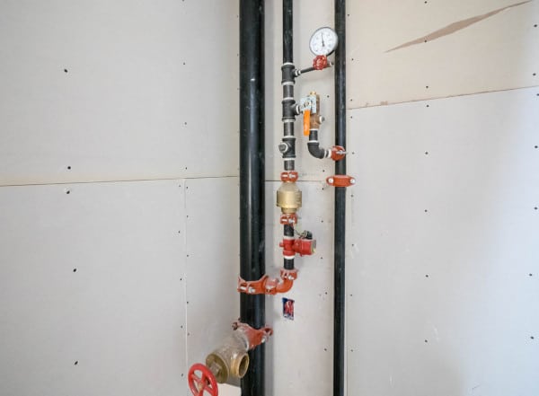
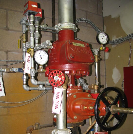
A fire sprinkler riser serves as a hub for drainage, tests, and system control
Installers combine risers with other required components to form riser assemblies (also called riser manifolds). The exact configuration varies, but nearly all of these fire sprinkler riser assemblies have:
- A vertical pipe—the riser itself
- A main drain
- An inspector’s test connection
- A control valve
- Pressure gauges
- A flow or pressure switch
Let’s look at each of these in turn.
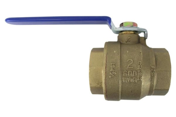
The main drain facilitates inspection, testing, and maintenance
All fire sprinkler systems feature a valve or valves designed to drain the system. In NFPA-compliant commercial and residential systems, these drains are often located at risers, where they can serve as a “main drain” for all connected piping. This drain often consists simply of a ball valve joined by pipes to the riser and a suitable discharge location. Listings aren’t required for these valves—but they must be approved by the authority having jurisdiction (AHJ).
Large residential (NFPA 13R) systems require a drainpipe at least 1” in diameter, along with a drain valve (typically of the same size). Home fire sprinkler (NFPA 13D) systems require a drain valve of 1/2” diameter or larger. Neither standard specifies that drains be located at the fire riser—only that they are placed on the system side (downstream) of the control valve.
Commercial (NFPA 13) systems may be drained at a series of auxiliary drains. But when properly placed and sized, a main drain can reduce the downtime required for inspection or repair. NFPA 13 prescribes the following minimum sizes for drains on supply risers and mains:
- 4” (100 mm) and larger risers or mains: 2” (50 mm) valves or larger
- 2 1/2”, 3”, 3 1/2” (65 mm, 80 mm, or 90 mm) risers or mains: 1 1/4” (32 mm) valves or larger
- 2” (50 mm) or smaller risers or mains: 3/4” (19 mm) valves or larger
For more on these and other requirements for drains at fire sprinkler risers, see:
- NFPA 13R (2016), section 6.9
- NFPA 13D (2016), section 7.2
- NFPA 13 (2019), section 16.9.1, 16.10.4-16.10.5, 16.10.6
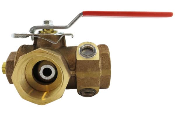
Test connections, often found on wet-pipe sprinkler system risers, help to ensure that alarms activate when the sprinkler heads discharge
Each sprinkler system features electronic or mechanical devices designed to activate when water flows through the system. An alarm test connection—also known as an inspector’s test connection—provides a means to test those devices.
These test connections are seen on fire sprinkler risers only in wet-pipe systems. Dry-pipe and preaction systems use a different type of test connection—called a trip test connection—located as far away from the riser as practicable. And deluge systems don’t require test connections at all. But in NFPA 13 and NFPA 13R wet-pipe systems, the alarm test connection must be at least 1” in diameter and can be placed anywhere downstream of the flow-sensing device it tests. It must also end in a smooth, corrosion-resistant orifice that flows water as slowly as the smallest sprinkler in the system.
Not all home fire sprinkler systems feature flow-sensing equipment—so, not all NFPA 13D risers feature test connections. When installed, these devices must have an orifice with the same characteristics and orifice size specified in NFPA 13 and 13R. However, the requirement for the connection to be at least 1” in diameter doesn’t apply.
Alarm test connections may be combined with drain valves, including the main drain. There are no special requirements for these combination test and drain valves: they need only be selected and installed in accordance with the NFPA’s provisions for test connections and drain valves. By combining the two, installers can reduce the riser’s size, the cost of materials, and the time required for installation.
For more on these and other requirements for test connections at wet-pipe system risers, see:
- NFPA 13, section 16.14.1
- NFPA 13R, section 6.10
- NFPA 13D, section 7.2
Control valves, found with every commercial riser, facilitate system shutdown as needed
Control valves start and stop the flow of water through fire sprinkler systems. When the sprinkler system is in service—as it should almost always be—these devices remain open. But when repairs or inspections require removing water from the system, the control valve closes to prevent new water from entering pipes downstream.
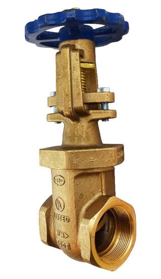
In NFPA-compliant sprinkler systems, these valves must be listed and must visually indicate whether they’re open or closed. As such, two types of control valves are commonly found with fire sprinkler risers:
- Outside stem & yoke (OS&Y) valves, which have a stem that retracts as the valve closes
- Butterfly valves, which have a brightly colored vane used to indicate whether the valve is open or not
In NFPA 13 systems, each water source (excluding water from the fire department connection) needs a listed indicating valve. In effect, this means that each commercial fire riser assembly has a control valve. But residential fire sprinkler systems work a little differently: many have a single control valve serving both sprinklers and domestic plumbing. Still, a separate valve may be featured at the riser if the valve is locked open, connected to a fire alarm system, or (in NFPA 13R systems) sounds “an audible signal at a constantly attended location” (section 6.8.2, 2016 edition).
For more on these and other requirements for drains at fire sprinkler risers, see:
- NFPA 13, section 16.9.3
- NFPA 13R, section 6.8
- NFPA 13D, section 7.1
Gauges on riser assemblies measure supply and system pressure, the pressure at main drains, and other key locations
NFPA 13 requires pressure gauges at the system main drain, main drains for floor control valves, and on both sides of a pressure-reducing valve (section 16.13.1, 2019 edition). Each gauge must have a thread connection of at least 1/4” in diameter. But gauges are also required at additional locations in the riser assemblies of wet, dry, preaction, deluge, and exposure protection sprinkler systems:
- Wet-pipe systems—at each system riser, as well as above and below alarm check valves or system riser check valves
- Dry-pipe systems—on the water and air side of a dry-pipe valve
- Preaction systems—above and below the preaction valve
- Deluge systems—below the deluge valve
- Exposure protection systems—below the control valve
Notably, the gauges required for exposure protection systems must be listed, while all other gauges in this list need only be approved by the authority having jurisdiction (AHJ).
Pressure gauges are somewhat less common at sprinkler risers in larger residential fire sprinkler systems: NFPA 13R requires only that gauges with shutoff valves be installed to measure both system pressure and supply pressure. And in smaller home fire sprinkler systems, gauges are only required with dry-pipe systems—and the only gauge that may be part of a riser assembly measures system air pressure.
For more, read “Fire Sprinkler Gauges: Where They Must Be and When to Replace Them.”
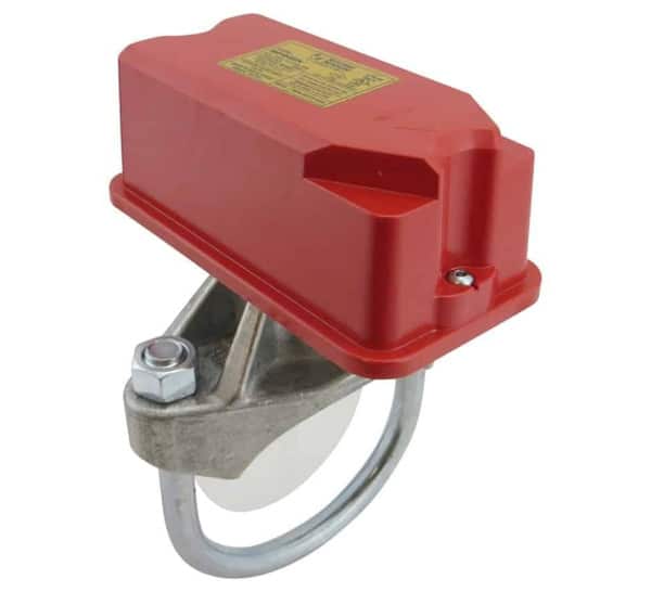
Expect water flow detection devices at all commercial and multifamily residential fire risers
As a fire sprinkler discharges, water flows out of the pipe, or branch line, it’s connected to. When that happens, water moves through the system riser to refill the branch line. These changes in flow and pressure are monitored at the riser by electronic devices called water flow switches. Discharge from even the smallest sprinkler will cause the device to send a signal to a fire alarm control panel—or sound an alarm directly—to let the building’s staff and/or occupants know that the sprinkler system has activated.
We’ve taken a look at the NFPA’s requirements for water-flow detectors in commercial, residential, and home fire sprinkler systems before. Three facts are especially salient when choosing these devices for fire risers:
- Most water flow switches may look the same—they’re not. Flow switches monitor for changes in water’s speed, while pressure switches watch for a change in pressure. While both can identify when a fire sprinkler system has activated, vane or paddle-type switches may only be used in wet-pipe systems; in other types of systems, a surge of pressure and flow could rip the vane or paddle off. Thus, pressure switches are used in dry-pipe, preaction, and deluge systems (and in wet-pipe systems with maintained excess pressure).
- Many home fire sprinkler systems don’t require water-flow alarms. Only homes without NFPA 72-compliant smoke alarms or detectors need a flow switch.
- NFPA 13 and 13R systems need listed water-flow switches. NFPA 13D systems may use non-listed water flow detection devices.
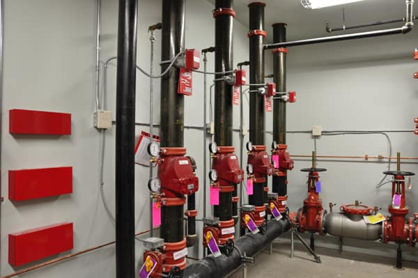
In commercial, residential, and even some home systems, fire risers assemblies condense essential components into an impressively small space
When it comes to risers, there’s plenty to consider. Setting aside the requirements of NFPA 13, 13R, and 13D—which we’ve only scratched the surface of—there’s the matter of choosing a riser configuration that’s not only code-compliant, but also cost-effective. That’s an issue we’ll tackle in part two of this series, where we dissect common riser assemblies in wet-pipe, dry-pipe, preaction, and deluge systems, and explore the benefits of pre-assembled riser kits.
If you’re looking to replace or improve on your sprinkler system riser, take a look at our riser kits and components, including:
- Pre-assembled commercial and residential riser kits
- Air and water pressure gauges and appropriately sized three-way valves
- Drain valves, including standard ball valves and test and drain valves
- Control valves, including butterfly valves and OS&Y valves
- Flow and pressure switches
Questions? Need help choosing the right fire sprinkler riser components? Call us at +1 (888) 361-6662 or email support@qrfs.com.
This blog was originally posted at blog.qrfs.com. If this article helped you, check us out at Facebook.com/QuickResponseFireSupply or on Twitter @QuickResponseFS.