

Threaded ports and additional trim transform a standard fire protection fixture into a labor-saving staple of the industry
Check valves play a simple—and essential—role in wet-pipe fire sprinkler systems. By keeping a supply of pressurized water at the ready, they guarantee that an activated sprinkler head can immediately combat a fire raging below. But “shotgun” check valves can do even more, streamlining initial sprinkler check valve installation and ITM (inspection, testing, and maintenance) throughout the life of the system.
In this article, we explain how shotgun check valves can single-handedly meet a wide variety of installation requirements for NFPA-compliant commercial and low-rise residential fire sprinkler systems.
If you’re searching for components for your system riser, you can browse our selection of tapped grooved check valves, shotgun riser check valve trim kits, thread seal tape, liquid thread sealant, grooved couplings, three-way valves, angle valves, and pressure gauges.
Sprinkler check valves placed at the system riser prevent backflow and pressure loss
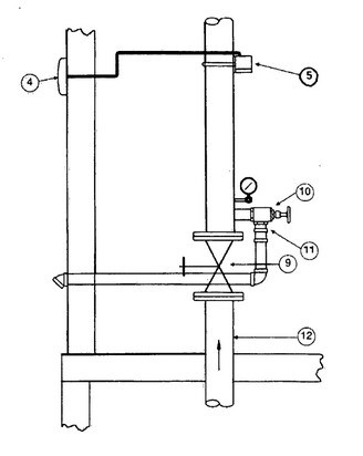
The system riser—a collection of components so essential that it’s often housed in a dedicated space—joins a fire sprinkler or standpipe system to a permanent water source. NFPA 13: Standard for the Installation of Sprinkler Systems explains that these risers consist of at least five components.
From the 2019 edition of NFPA 13 [underlines added]
3.3.215 System Riser. The aboveground horizontal or vertical pipe between the water supply and the mains (cross or feed) that contains a control valve (either directly or within its supply pipe), a pressure gauge, a drain, and a waterflow alarm device.
The system riser provides access to equipment used in inspection, testing, and maintenance—all from a single, central location. And with a properly configured bell or gong (a “waterflow alarm device”), installers ensure that an alarm sounds when fire sprinklers activate.
Contractors often install one other essential component at sprinkler system risers: a check valve. These devices prevent contamination of municipal water supplies (or other water sources) by ensuring that water flows into—but never out of—sprinkler pipes. In wet-pipe sprinkler systems, which are filled with a supply of pressurized water, check valves also prevent pressure loss.
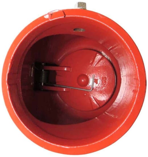
Nearly all sprinkler check valves have the following features in common:
- A body, which houses the components within
- A clapper that opens and closes in response to changes in pressure
- A valve seat designed to form a water-tight seal
Their bodies join to pipes with flanged, grooved, or threaded ends. Each of these joining methods has an impact on sprinkler check valve installation—with grooved connections and couplings offering substantial advantages in terms of speed.
“Shotgun” check valves for sprinkler systems connect directly to NFPA-required gauges and drains
In a 1998 white paper entitled “Impact of Wet-Pipe Fire Sprinkler Systems on Drinking Water Quality,” the American Water Works Association (AWWA) described “shotgun risers” as one of the three most typical arrangements in a fire sprinkler system. These system risers had:
- A listed swing check valve
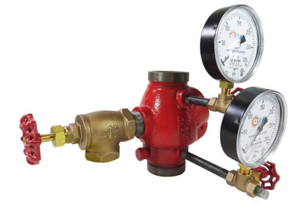
- Two pressure gauges—one for measuring the pressure of the supply and another for the pressure stored in sprinkler system piping
- A flow switch or sensor used to activate an alarm bell
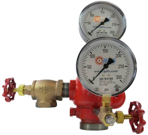
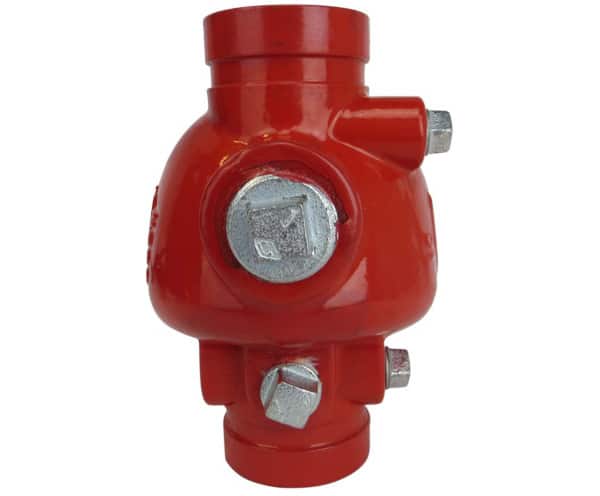
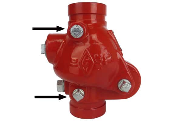
Sprinkler check valves used in typical shotgun riser assemblies differ slightly from standard check valves. In addition to a body, clapper, and seat, these “shotgun check valves” include:
- Two threaded ports (typically with National Pipe Thread, or NPT) designed to connect to gauges using pipe nipples and three-way valves
- A larger threaded port—as big as 2”—for connection to the main drain valve (typically, an angle valve)
- Plugs to close off these ports
By removing those plugs—and adding a series of code-required valves and gauges—these check valves can serve as a sprinkler system’s hub for essential ITM tasks, including:
Shotgun riser check valves feature two code-mandated pressure gauges
In wet-pipe systems—the most common sprinkler system type—shotgun check valves facilitate swift installation of gauges required at the system riser. Those requirements apply to commercial systems under the purview of NFPA 13, although similar rules govern low-rise residential occupancies addressed in NFPA 13R: Standard for the Installation of Sprinkler Systems in Low-Rise Residential Occupancies (see section 6.12 in the 2016 edition).
From the 2019 edition of NFPA 13
8.1 Wet Pipe Systems
8.1.1.1 An approved pressure gauge conforming to Section 16.13 shall be installed in each system riser.
8.1.1.2* Pressure gauges shall be installed above and below each alarm check valve or system riser check valve where such devices are present.
8.1.1.2.1 A single pressure gauge shall be permitted to be installed on a manifold below multiple riser check valves or alarm check valves.
8.1.1.2.2 Pressure gauges below check valves required by 16.9.11 and 16.15.2.2(1) shall not be required.
In NFPA-compliant commercial and low-rise residential systems, at least two gauges are required whenever there’s a check valve at the system riser: one upstream and one downstream. Shotgun check valves provide ports for both, making them ideal for buildings that rely on a single riser.
Facilities with multiple risers don’t need one upstream (or supply-side) gauge with each check valve—just one at the manifold they connect to. However, each of these sprinkler check valves still needs a downstream (or system-side) gauge. Installers with a shotgun-capable check valve can simply leave the supply-side ports plugged and add gauges to the system-side ports.
An angle valve with an adjacent pressure gauge can satisfy NFPA drainage requirements
NFPA 13 requires installers to design commercial sprinkler systems so that every section can be drained (section 16.10.4.1). It also recommends that sprinkler system piping be arranged to allow the entire system to drain from a single source—the main drain valve. As such, this valve is typically located at the fire sprinkler system riser.
In section 16.10.4.2, NFPA 13 prescribes the following drain sizes for supply risers:
- 2” risers (and smaller): 3/4” drain valve
- 2 1/2” to 3 1/2” risers: 1 1/4” drain valve
- 4” risers and larger: 2” drain valve
Most shotgun-style sprinkler check valves are sized in accordance with these guidelines. As such, installing an appropriate drain is as easy as removing a plug and installing the corresponding nipple and valve.
Further, each main drain in a commercial fire sprinkler system needs a pressure gauge nearby—a role that may be suitably played by the system-side gauge attached to a shotgun riser check valve.
From the 2019 edition of NFPA 13
16.13.1 A pressure gauge with a connection not smaller than 1⁄4 in. (6 mm) shall be installed at the system main drain, at each main drain associated with a floor control valve, and on the inlet and outlet side of each pressure-reducing valve.
Low-rise residential systems are installed in accordance with similar—though not totally identical—guidelines, including:
- Each fire sprinkler system needs a drain on the system side of a control valve (NFPA 13R 6.9.1, 2016 edition)
- Drain pipes must have at least a 1” nominal diameter, along with a valve (6.9.2-6.9.3)
- Each main drain needs a gauge, and that gauge must have a thread connection 1/4” or larger (5.2.15)
Shotgun check valves for sprinkler systems include mandated gauge trim
In NFPA-compliant commercial sprinkler systems, the pressure gauges required for the system riser and main drain attach to valves before connecting to a riser or check valve. (Identical provisions for low-rise residential occupancies can be found in NFPA 13R, section 5.2.15.)
From the 2019 edition of NFPA 13
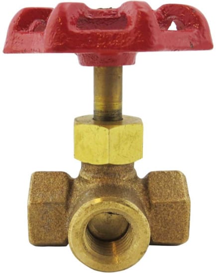
16.13.2 Each gauge connection shall be equipped with a shutoff valve and provisions for draining.
16.13.4 Gauges shall be installed to permit removal and shall be located where they will not be subject to freezing.
Three-way valves can meet parts of both requirements. These “shutoff valves” can start or stop flow to the gauge (facilitating their removal) and drain water through an additional outlet.
Alarm check valves for sprinkler systems offer similar, but not identical, features and benefits
One other check valve for wet-pipe fire sprinkler systems has many, if not all, of these same features: the alarm check valve. The difference between the two has to do with the type of water flow alarm each uses.
Alarm check risers rely on a water-powered alarm bell, or water motor gong. Water flows through a port, called an alarm port, to a series of pipes and other devices. This eventually ends in a pressurized stream of water that spins a striker and sounds the gong. Shotgun risers, on the other hand, rely on an electronic (but still water-activated) switch downstream.
Both set-ups perform nearly the same function, but each arrangement has slightly different advantages:
- Alerting staff to malfunctions. AWWA’s 1998 white paper notes that alarm check valves will sound an alarm if corrosion or other wear jams the clapper in the open position. Waterflow detectors, however, only sound when water moves at a specified rate.
- Providing information to firefighters. An electric bell produces the same sound each time it’s activated, but the striker in a water motor gong rotates more slowly at lower pressures. Firefighters may be able to identify water pressure problems simply by listening to the sound of the gong. As a result, some authorities having jurisdiction (AHJs) may prefer or require water motor gongs.
- Compatibility with fire alarm systems. Many electronic flow switches installed with shotgun risers can activate a local alarm bell and send a signal to a fire alarm control panel. Water motor gongs can’t do that (although a flow switch may be added to an alarm check riser that can).
- Maximum distance from the riser to the bell. Pipes leading to water motor gongs may not exceed 75 feet in total length; those devices may not be placed more than 20 feet higher than the check valve.
Shotgun sprinkler check valve installation requires little time and few tools
Contractors looking to assemble a shotgun sprinkler check valve can either purchase components individually (roughly 13 pieces, by our count) or order complete riser check valve kits. The latter option can expedite installations involving a single system riser with low-to-moderate water pressures. For installations involving multiple risers connected to a single manifold, installers may prefer to order tapped and plugged groove check valves, along with necessary trim and drain components like:
- Thread seal tape or liquid thread sealant
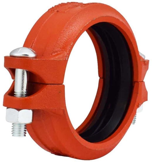
- Grooved couplings and coupling grease
- Three-way valves
- Angle valves
- Pressure gauges
- Pipe nipples and plugs
With these parts handy, the installation of a shotgun riser check valve for a sprinkler system is straightforward. The process for adding a check valve with grooved pipe ends looks something like this:
- Flush the piping to remove debris.
- Choose a location for installation. In general, check valves should be installed at a distance of at least 5 times the pipe diameter downstream from pumps, reducers, and pipe fittings.
- Install the valve in accordance with the manufacturer’s instructions. Different models install vertically (arrow-up), horizontally, or in either orientation. The arrow imprinted on the body must point in the direction of flow.
- Secure the valve to the riser with grooved couplings.
- Remove the pipe plugs from the tapped holes.
- Apply PFTE tape or liquid sealant to the male ends of gauge and valve nipples. Thread them into the tapped holes.
- Repeat this process for other remaining male-ended devices (plugs and gauges).
- Test the system in accordance with NFPA guidelines and local regulations.
QRFS’s wide-ranging catalog of wet-pipe riser equipment is designed to help contractors get through the installation process quickly and safely. Our stock includes UL-listed grooved check valves in sizes from 2” to 6”, grooved couplings to match, riser kits, and a full selection of components and accessories for every step of the process.
Browse our selection of check valves and check valve trim kits.
Questions? Call us at +1 (888) 361-6662 or email support@qrfs.com.
This blog was originally posted at blog.qrfs.com. If this article helped you, check us out at Facebook.com/QuickResponseFireSupply or on Twitter @QuickResponseFS.