

Fire pumps can be crucial to sprinkler system performance—and it’s essential to get the right machine for the job
Look closely at any tall building, and you’ll probably find a sign that says “fire pump room” or maybe a plate next to the standpipe connection with fire pump pressure information. Though hidden away from the general public, the fire pump is one of the most critical components of many fire sprinkler systems—and undoubtedly the most expensive. Its job is to provide necessary water flow and pressure to fire sprinklers (and standpipes).
A fire sprinkler system cools and wets a room during a fire, controlling its spread and preventing deadly flashovers. This, of course, depends on having enough water flow and pressure. And larger buildings with more extensive fire areas may need a fire pump to augment the water supply.
In some cases, such as in rural areas, the municipal water just doesn’t have enough volume and pressure. In other places, the water supply could be a well, pond, tank, or another source that isn’t pressurized. Perhaps most commonly, high-rise buildings need fire pumps to overcome the force of gravity.
A fire pump boosts the water, so sprinklers have enough flow and pressure to provide fire control. But what does “enough” mean? When is a fire pump necessary, and how big should it be?
This article looks at how fire pumps are sized based on the criteria listed in core standards: NFPA 13: Standard for the Installation of Sprinkler Systems (2019 edition) and NFPA 20: Standard for the Installation of Stationary Pumps for Fire Protection (2019 edition).
Sprinkler system demand and the water supply curve
Hydraulic design simplified
Every fire sprinkler system needs a reliable water supply. Usually, this means a municipal water connection, but NFPA 13 allows tanks, ponds, and wells to serve as water supplies as well (5.2). Whatever the source, it needs to be automatic—in other words, function without human input—and push water through sprinklers with a sufficient flow rate and pressure to provide fire control.
Determining how much flow and pressure is enough is the core question of fire sprinkler system design. To calculate this, engineers use a concept called a design area, which is a sample of the larger building. Engineers assume that every sprinkler in the design area will activate in a fire and calculate the amount of water flow and water pressure needed to do it. NFPA 13 defines how large a design area must be (19.3.3.1.4) and how many sprinkler heads it must contain (19.3.3.2.3.2).
The design area is meant to be a worst-case scenario in terms of hydraulics. “Worst-case” can represent the highest point or the furthest point. Gravity and friction from pipes both fight against water pressure, so height and distance ultimately inhibit pressure. Additionally, “worst-case” can mean “most flammable,” a variable measured with categories called hazards. Typically, several design areas are tested to find the true hydraulic worst-case scenario.
Having identified the design area, engineers refer to NFPA 13’s requirements for water density (GPM/ft2) and calculate the required flow and, ultimately, the required pressure. These two data points—necessary pressure and flow—are known as system demand.
For more information on how this process works, you can refer to our articles on the elements of sprinkler system design and the amount of pressure required for a sprinkler system.
Comparing water supply and system demand
After determining system demand, the crucial question is whether the water supply is up to meeting that demand.
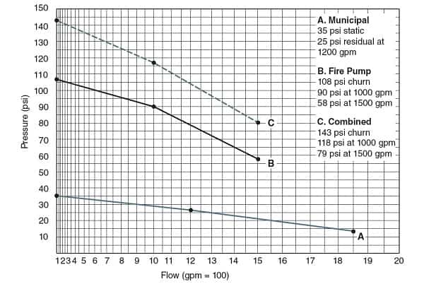
The capacity of municipal waterworks, according to NFPA 13 (5.2.2.2), is measured with a fire hydrant flow test and presented as a water supply curve. A flow test is conducted using at least two fire hydrants; a pressure gauge is affixed to one, and the other is opened to flow water. Because pressure and flow are interrelated, two data points are required: static pressure (with no flow) and residual pressure (with the flow hydrant open wide).
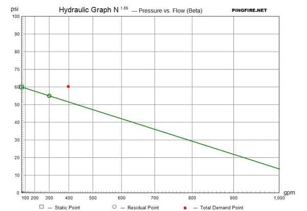
Comparing system demand and water supply capacity is as simple as plotting them both on the same graph. If the point of system demand falls below the water supply curve, the supply is sufficient—usually. Some jurisdictions mandate a safety factor—a buffer of a few PSI—between supply and demand, though NFPA 13 does not explicitly require this.
If system demand is above the water supply curve, the water supply is insufficient. Sometimes, designers can resolve this by re-engineering the fire sprinkler system—choosing different sprinkler heads, resizing pipes, etc. But frequently, a fire pump is required to make up the difference, especially in high-rise buildings.
Fire pump performance curves
Fire pumps are an essential part of any fire sprinkler system that requires them, making up the difference between the water supply and system demand. Plus, they are easily the costliest and most complicated single piece of equipment in a system. So if you’re a facility manager, it pays to know about your fire pump.
The basics of fire pumps
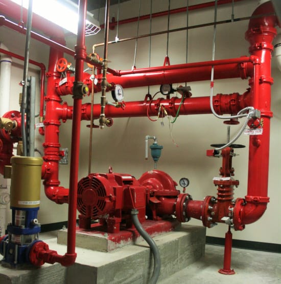
Specifically designed, tested, and listed for fire protection, fire pumps propel water through pipes, boosting the pressure and flow. They are installed between the water supply connection and the main riser of a fire sprinkler system. There, they usually sit idle, switching on when the activation of a fire sprinkler causes a drop in system pressure.
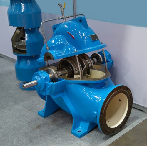
While all pumps perform the same function, there are many options to choose from. Here, we’ll focus on centrifugal pumps, a common type. Centrifugal pumps use an impeller (similar to a propeller) to accelerate water into and out of the pump housing.
Pump size is measured in three ways, all of which determine capability. These are: suction-side (inlet) diameter, discharge-side (outlet) diameter, and impeller diameter. These three pump dimensions are represented in a shorthand that looks like this:
3 x 2 x 11
Above, the suction is 3 inches, the discharge is 2 inches, and the impeller diameter is 11 inches.
As we’ll discuss shortly, impeller diameter directly affects the ability of a pump to create flow and pressure—a bigger impeller means more of both.
Fire pump performance curves
Every fire pump is rated for a particular flow rate and corresponding pressure. For instance, a pump might be rated to produce 200 GPM at 170 PSI. However, the actual flow rate a pump experiences can vary. For example, the flow rate can be very high if many fire sprinklers activate during a fire. And if the pump triggers accidentally (or during a fire pump test), the flow rate can be zero.
Fire pump performance curves represent fire pump performance in a variety of situations. These curves show how much pressure a pump produces at a given flow rate and include, at a minimum, these three data points:
- Churn pressure (pressure when the pump is running, but no water is flowing)
- Pressure at rated flow (“100%”)
- Pressure at 150% rated flow
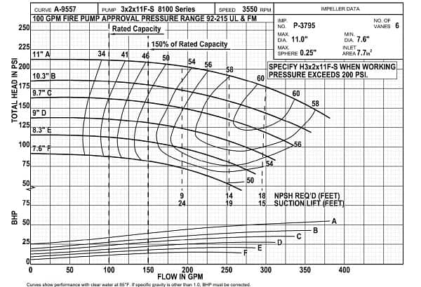
This data represents the range of a pump’s possible performance, from churn to the max allowable flow. This can be far beyond the so-called “100% rated flow.” For centrifugal pumps, NFPA 20 specifies that sprinkler system flow demand should never exceed 150% of the rated flow of a pump (4.10.2)—sometimes called the overload point.
You can read more about pump performance and testing in our previous blog.
To size a fire pump, designers combine pump curves and water supply curves
Once engineers determine that a fire pump is needed, they have to pick one that’s the right size. The first consideration when sizing a fire pump is making sure that it’s big enough. In other words, a pump is only useful if it produces enough flow and pressure.
Figuring this out is another piece of arithmetic. First, designers evaluate multiple fire pump performance curves, plotting the water supply curve and each pump performance curve on the same graph. Then, they combine the curves by adding them together, producing a new curve that shows the performance of the water supply with the pump.
The performance of multiple pumps and impeller sizes with the water supply will often have to be calculated to find a combination that works well. There are also more advanced considerations to pump performance, including efficiency and horsepower, but we’re focusing on flow and pressure here.
A pump must be big enough to do its job. However, pumps can also be too big. Excessive pressure can damage a fire sprinkler system. Per NFPA 13, above-ground fire sprinkler components must be rated to at least 175 PSI (7.1.2); if the water pressure exceeds this, special design measures are needed to prevent system failure.
Beyond the risk of water damage, it bears repeating that fire pumps are hugely expensive pieces of equipment. A pump that’s too powerful can be a lot of wasted money.
Fire pumps provide essential flow and pressure to sprinkler systems and standpipes
The hydraulic design of a water-based system is all about supply and demand. The water supply for a fire sprinkler system—usually a city waterworks—has a finite capacity, and the system demands a specific flow rate and water pressure to function correctly. So, if the water supply doesn’t meet system demand on its own, a fire pump may be necessary.
System designers evaluate different pumps based on their performance and the given water pressure to size them correctly. And remember: this delicate balancing act is only one essential component of complex water-based system design!
This blog was originally posted at blog.qrfs.com. If this article helped you, check us out at Facebook.com/QuickResponseFireSupply or on Twitter @QuickResponseFS.
This article is very helpful and easy to understand. Thank you for sharing!
Sir,
Can you please help me how to identify the following:
20 floors building
1. Fire pump size and hp
2. Jockey pump size and hp
3. Cistern tank capacity
4. Gpm
Thank you very muh!
Roan — Unfortunately, specifically sizing a fire pump is a fairly detailed endeavor that relies on having very specific information about the system, including the hydraulic demand of the most challenging area of the sprinkler system. Thus, a fire sprinkler design professional must provide specs and usually sizes the pump and needed tank capacity. We suggest you contact a local fire sprinkler system design pro or inspection, testing, and maintenance pro, and they will directly assist you or point you in the right direction. Best of luck!
the max. flow is 150% of the rated flow rate acocording to NFPA @ 65% of the rated pressure….
what about the min. flow ? is it 60% of the rated flow or what????????
PLZ, your answer must be in accordance to NFPA 20
Ahmed — For specific standards and code questions like yours, you can try our Ask a Fire Pro service. Click the link to submit your question with some information about your building, and a fire protection professional will provide an answer based on best practices, standards, and codes. Our pros include AHJs, contractors, engineers, and code experts with 150+ years of combined experience!
Pumps with flat curves can save how high the prvs are used.
By flatening the curve( 0 fliw, churn,) approx 2 levels per 10 psi- prvs can be reduced.