

Sprinkler water pressure is essential—but how much is enough?
A building’s water supply, whether it’s the municipal waterworks, a well, or a tank, must have enough capacity and pressure to meet the demands of its fire sprinkler system—and a pump must often augment pressure. When a system lacks an adequate water supply under enough pressure, it may be considered impaired under the guidelines of NFPA 25: Inspection, Testing, and Maintenance of Water-Based Fire Protection Systems.
But how much flow and pressure does a sprinkler system need? Essentially, designers determine this number by assessing the flow and pressure demands required to control fires in particularly challenging areas of the system. Sprinkler designers do not plan for every sprinkler in a building to activate at once. As the NFPA 13: Automatic Sprinkler Systems Handbook (2019 edition) explains:
“The water supply must be capable of meeting the most hydraulically demanding area of the systems.”
Engineers answer the question of pressure demand from two directions. A top-down approach (from the sprinkler heads) determines the system’s needs. And a bottom-up approach (from the water supply hookup) determines the water supply’s capacity and the pressure and flow losses it experiences in transit.
In this article, we explain:
- How sprinkler water demand is determined using design areas
- How the water supply capacity is determined from a flow test
- How friction, turbulence, and gravity fight against the supply’s pressure
Remember, this is complex work that must be done by qualified fire protection professionals. Fire sprinkler systems are life-saving infrastructure—they aren’t DIY projects.
Determining sprinkler water pressure-demand with design areas
Fire protection engineers design sprinkler systems to control or suppress fires in the most challenging locations within a system.
The building the system is protecting may have a variety of different hazards and fuel loads. The sprinkler heads and piping are sized and selected in anticipation of controlling these various hazards. The most demanding set of sprinklers in each of these areas is called a design area. Commonly, these heads are the furthest away from the water supply.
By identifying the design areas with the greatest hydraulic demand in the event of a fire, designers can determine the system’s overall flow and pressure requirements.
What constitutes a “difficult design area” basically stems from two factors: remoteness (because distance and gravity make it harder to deliver water) and occupancy hazard (which describes the fuel load and other factors that may call for more water to suppress a fire), or both.
If a system has sufficient pressure to deliver the required flow to the most challenging design areas, it can certainly meet the hydraulic demands of any other section. The place with the highest hydraulic demand isn’t always obvious, so multiple design areas are often analyzed.
To determine the demand of a sprinkler system, fire protection engineers follow this rough process:
- They identify the hazard levels in the building based on fuel load.
- Based on hazard level and remoteness, they identify demanding design areas.
- Based on the design area size and hazard, designers determine the required flow rate.
- Flow rate allows designers to determine pressure demands.
- The hazard level also sets sprinkler spacing. It, along with some building construction considerations, determines the maximum coverage area per sprinkler. This helps determine how many sprinklers are in the design area, and how they will utilize the flow at the required pressure.
Occupancy hazard depends on fuel load
Section 19.3.1.2.4 of NFPA 13: Standard for the Installation of Sprinkler Systems categorizes buildings or parts of buildings into six occupancy hazard classifications. These are:
- Light Hazard
- Ordinary Hazard (Group 1)
- Ordinary Hazard (Group 2)
- Extra Hazard (Group 1)
- Extra Hazard (Group 2)
- Special Occupancy Hazard
Many factors contribute to the assignment of these classifications:
From the 2019 edition of NFPA 13
19.3.1.2.3 Occupancies or portions of occupancies shall be classified according to the quantity and combustibility of contents, the expected rates of heat release, the total potential for the energy release, the heights of stockpiles, and the presence of flammable and combustible liquids, using the definitions contained in 4.3.2 through 4.3.7.
These occupancy hazard categories are reminiscent of classes used in other NFPA documents. NFPA 101: Life Safety Code, for instance, also identifies occupancy hazards. However, the six categories named by NFPA 13 apply only to the design process of fire sprinkler systems. The standard specifies that they “shall not be intended to be a general classification of occupancy hazards” (4.3.1.2).

Placing a facility or parts of a facility into a hazard category is more complicated than it sounds. Steven Scandaliato, NFPA 13 committee member, explains that it takes critical thinking and thorough code knowledge to classify even a seemingly simple retail project. Numerous factors can change the occupancy hazard or invoke special rules. As we demonstrate in the next section, basically everything depends on getting this part right.
That said, here are some non-comprehensive lists of facilities that often fit into the various occupancy hazard categories according to NFPA 13 (A 4.3.2-6). Note that these are suggested (typical) classifications in the Annex and not part of the enforceable portion of the standard:
Light Hazard
- Churches
- Clubs
- Educational
- Hospitals, including veterinary facilities
- Institutional
- Kennels
- Museums
- Nursing or convalescent homes
- Offices, including data processing
- Residential
- Restaurant seating areas
- Theaters and auditoriums
- Unused attics
Ordinary Hazard (Group 1)
- Automobile parking and showrooms
- Bakeries
- Beverage manufacturing
- Canneries
- Dairy products manufacturing and processing
- Electronic plants
- Glass and glass products manufacturing
- Laundries
- Restaurant service areas
- Porte cocheres
- Mechanical rooms
Ordinary Hazard (Group 2)
- Agricultural facilities (inc. barns and stables)
- Cereal mills
- Chemical plant—ordinary
- Dry cleaners
- Libraries (large stack room areas)
- Machine shops
- Metalworking
- Mercantile
- Paper and pulp mills
- Piers and wharves
- Stages
- Textile manufacturing
- Tire manufacturing
- Carpentry areas
Extra Hazard (Group 1)
- Aircraft hangers
- Combustible hydraulic fluid use areas
- Die casting
- Metal extruding
- Plywood and particleboard manufacturing
- Printing with inks with low flashpoints
- Rubberworks
- Sawmills
- Textile work
- Plastic foam upholstering
Extra Hazard (Group 2)
- Asphalt saturating
- Flammable liquids spraying
- Flow coating
- Open oil quenching
- Plastics manufacturing
- Solvent cleaning
- Varnish and paint dipping
Note that high-piled storage (4.3.7) is classified separately by rules found in chapters 20 through 25 of NFPA 13. In addition, the “Special Occupancy Hazard” category involves occupancies (often, particularly dangerous ones) governed by other NFPA standards. These can include flammable liquids, aerosols, flammable sprays, chemical laboratories, and much more.
Calculating the required flow for the design area
Two factors determine the required flow rate: design area hazard level and size. After a designer identifies the occupancy hazard(s) of a facility, the next step is to identify relevant design areas and determine their size.
Design area size can vary, but there are minimum sizes (19.3.3.1.4) that must be met. For Light and Ordinary Hazard areas, the minimum size is 1,500 ft2. For Extra-Hazard areas, the minimum size is 2,500 ft2. Depending on the location, several adjustments to the design area’s effective size are needed or allowed. These include required increases in size because of:
- Sloped ceilings (3.3.2.4)
- Use of dry pipe or double-interlock preaction systems (3.3.2.5)
- Unsprinklered combustible concealed spaces adjacent to the design area (3.3.1.5.1)
When specific conditions are met, the use of quick-response sprinklers enables designers to reduce the design area size (19.3.3.2.3.1). Also, section 19.3.3.2.6 allows a 25 percent reduction when high-temp heads are used in an extra-hazard setting, but the area can go no lower than 2,000 square feet.
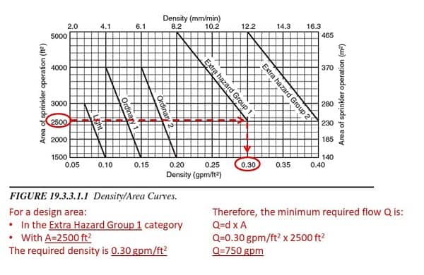
Once the design area size is known, figuring out the required flow is straightforward. NFPA 13 provides density/area curves. Professionals simply select the curve for the appropriate hazard level and use the size to find the corresponding water density. Then, they use this formula to calculate the required flow:
Q=d x A
Where:
Q=minimum required flow (GPM)
d=water density (GPM/ft2)
A=area (ft2)
Here’s an example of how the density/area curves can be used to calculate the flow required for a 2,500 ft2 Extra Hazard Group 1 design area:
Selecting sprinkler heads and determining the required pressure
Once the minimum required flow is known, the minimum required pressure can be determined. Pressure and flow are both tied to a value called K-factor, which describes how much water flows from a nozzle (like a sprinkler head) at a given pressure. Every fire sprinkler has a specific K-factor. The relationship between pressure (P), flow (Q), and K-factor (K) is:
Q=K√P
To determine the required pressure for the room, the engineer figures out the flow through each sprinkler head in the space. Practically speaking, different sprinkler heads in the room may experience different pressures and flow rates. But for illustrative purposes, we will divide the total required flow by the number of sprinkler heads to get the necessary flow from each head. Then, a K-factor is selected for the sprinklers, and the pressure is calculated.
Let’s return to our 2,500 ft2 extra-hazard room and assume it uses 20 sprinklers with K=8.0. From the “Density/Area Curves” graphic above (Figure 19.3.3.1.1), we know that the required flow for the total design area is 750 gallons per minute (GPM).
The minimum flow from each sprinkler head is:
Q= 750 GPM ÷ 20 sprinkler heads = 37.5 GPM from each sprinkler head
The required pressure at each sprinkler head is:
P = (Q ÷ K)2
P = (37.5 GPM ÷ 8.0 k)2
P = 21.97 psi
Remember, a qualified engineer must do this work. The math may not seem complicated, but, as Steven Scandaliato explains, everything else comes out wrong if you don’t get the density right. To do that, you have to understand the complexities of fuel load and occupancy hazard. That takes an expert.
Professionals gauge the available pressure with a flow test
Another core question in sprinkler system design is how much water pressure and flow are available for a sprinkler system. Determining the hydraulic demands of a system is crucial, but designers also need to know the hydraulic capacity to make decisions. For many facilities, the capacity reflects the municipal water supply’s capacity, but other structures rely on tanks, wells, lakes, or other reservoirs.
Water supply capacity is determined through a flow test. NFPA 13 states that “The volume and pressure of a public water supply shall be determined from water-flow test data or other approved methods” (5.2.2.2). These flow tests are conducted using two nearby fire hydrants. To carry out a flow test, engineers and ITM professionals use pitot gauges to measure hydrant pressure. Note that NFPA 291: Recommended Practice for Fire Flow Testing and Marking of Hydrants provides guidance on conducting these tests.

This video offers a brief demonstration of how a flow test is conducted:
The residual reading at hydrant A is used to accompany the flow value obtained from hydrant B. These two key data points, when plotted on a logarithmic-scaled graph or chart, establish the “curve” used to predict flow at a given pressure, or pressure at a given flow.
The test tells you what is available at the pipe where the test was conducted, not at the base of the riser. The designer calculates the system’s demand all the way back to where the water supply is “known”—which is typically the line where the test was conducted (e.g., the city water main in the street).
Whatever pressure is available, some of it is lost as water travels through the building. In the next section, we explain what causes pressure loss and how engineers account for it in hydraulic calculations.
QRFS has the tools for qualified workers to carry out flow tests. We have test kits with the gauges, pitot tools, and nozzles needed for a flow test, plus fire hydrant wrenches for opening the valves.
Accounting for pressure loss in a fire sprinkler system
The pressure available at the hydrant or the fire sprinkler riser is not what is available at a given sprinkler head. Factors like the size of the pipe and what it is made of effect the pressure that arrives at a sprinkler. Pressure loss (sometimes called head loss) between the water supply and the sprinkler head is caused by:
- Pipe friction
- Turbulence around or through fittings and valves
- Elevation changes (gravity)
Besides these factors, designers have to account for the demand firefighters will place on the water supply when they hook hoses up to the fire hydrants (19.2.6.2).
In other words, the available pressure at sprinkler heads is the available pressure at the source (measured in a flow test) minus the head loss and other demands on the system.
Accounting for pressure loss due to friction
As water travels through pipes, it experiences friction against the pipe walls. This friction works against the pressure pushing water through the system.
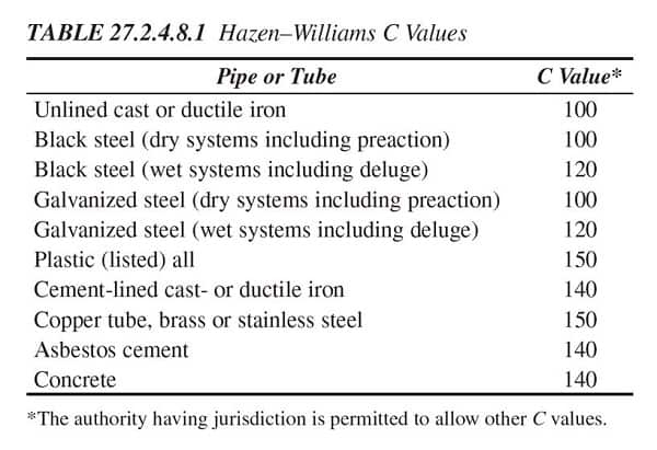
Friction loss depends on several factors. First, faster-flowing water experiences more friction loss. Second, smaller-diameter pipes can create more friction loss per foot at a similar flow rate. Finally, different types of pipes generate more or less friction based on how “rough” they are. Roughness is measured by the friction coefficient C (aka “C-factor”). The friction coefficients of standard pipe materials are listed in the table below:
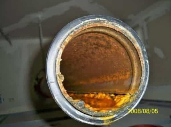
Pipes get rougher as they age, corrode, and scale. The practical consequence of this is that available water pressure can decrease over time with the degradation of pipes. Facility managers should take steps to prevent corrosion of pipe systems—and not just for the sake of maintaining water pressure. Corrosion reduces the lifespan of sprinkler systems and vastly increases the costs of maintaining them. Learn more about pipe corrosion, its effects, and prevention in our previous blog.
To calculate friction loss with these factors, NFPA 13 approves the use of the Hazen-Williams formula:
From the 2019 edition of NFPA 13
27.2.2.1.1 Pipe friction losses shall be determined on the basis of the Hazen-Williams formula, as follows:
p = (4.52Q1.85) ÷ (C1.85d4.87)
where:
p = frictional resistance (psi/ft of pipe)
Q = flow (GPM)
C = frictional loss coefficient
d = actual internal diameter of pipe (in.)
In this case, Q represents the flow of water from an activated sprinkler head. As more sprinkler heads open, flow and pressure losses due to friction both increase.
Let’s return to our hypothetical Extra-Hazard room with a 750 GPM flow demand. Say this room is fed by 100 ft. of 4” nominal Schedule 40 steel pipe (inner diameter= 4.026”) with a C-factor of 120. Ignoring the length of cross-mains and branch lines, the head loss due to friction that would occur if all sprinklers in this room activated is calculated as follows:
p = (4.52Q1.85) ÷ (C1.85d4.87)
p = (4.52 x 750 gpm1.85) ÷ (1201.85 x 4.026 in.4.87)
p = 0.15 psi per foot of pipe
Total pressure loss = 0.15 x 100 ft. = 15 psi.
Though more precise methods are available, the Hazen-Williams formula is a simple method for calculating friction loss. NFPA 13 approves this formula except where antifreeze additives are involved in up to 40-gallon systems. When these chemicals are present in larger systems, fluid viscosity is affected. See section 27.2.2.1.3 for instructions in this case.
Accounting for sprinkler water pressure loss due to turbulence at fittings and valves
Pipe fittings (tees, elbows, etc.) create turbulence in the water flow that causes pressure loss. These losses are not friction losses per se. However, they are calculated in terms of the equivalent friction loss of a length of pipe. NFPA 13 (27.2.3.1.1) says that losses due to certain fittings and valves should be understood in terms of Schedule 40 steel pipe based on the table below:
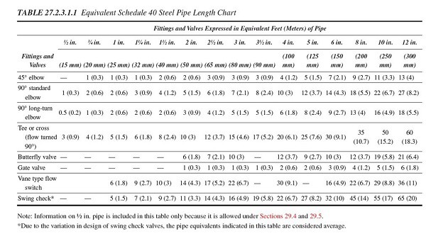
Based on this table, you can see that a standard 90-degree elbow in the 4″-nominal size creates the same frictional resistance as 10 ft. of Schedule 40 steel pipe of the same size. In this case, that would mean another 1.5 psi lost.
Not all pipe is Schedule 40 steel, of course. NFPA 13 allows designers to calculate the equivalent length for other pipe schedules and C values based on multipliers found in Table 27.2.3.2.1 (for different C-values) and paragraph 27.2.3.1.3.1 (for different sizes).
When the type of fitting or device is not found in NFPA 13’s tables (or when it is advantageous), the designer may (27.2.3.1.1) use equivalent lengths provided by the fitter or device manufacturer.
Sprinkler water pressure loss from gravity
When water has to travel vertically upward in a pipe, the force of gravity counteracts the pressure that conducts it (pressure also increases when water moves vertically down). The head loss due to gravity for water is 0.433 psi for every foot of vertical elevation. Besides the friction losses, our example with the 100-ft. riser would lose 43.3 PSI simply because of height.
Pressure-wise, things aren’t looking good for the Extra-Hazard room in our example. Combined head losses are up to 58.3 psi (43.3 psi + 15 psi) without counting any devices, cross-mains, or branch lines. With the actual demand (21.97 psi), the water supply needs to deliver over 80 psi at the riser. Water pressures above 80 psi can cause plumbing problems, so it’s unlikely that a municipal water supply will meet this demand.
The system will need a pump!
Note: Remember, the purpose of our Extra Hazard example is to demonstrate how water pressure demands and losses work; it doesn’t include other parts of the design process, like laying out a sprinkler system or correctly sizing the pipes.
Proper pressure and flow are essential for a fire sprinkler system
Without minimum water pressure and flow, fire sprinklers cannot work as intended. They won’t be able to put out enough water to suppress fires. If the pressure at a sprinkler head is below a bare minimum of 7 psi, the water won’t be able to push out the sprinkler cap when the heat-sensitive bulb breaks. This is why no design can have less than a 7 psi “starting pressure” for any sprinkler.
How do engineers make sure the water supply matches the demand? What if, as was the case in our example, the pressure demand exceeds the pressure capabilities of the supply? Depending on whether the project is new construction or a revision, engineers have several ways to make the numbers match up. They can:
- Manage pressure demand by using quick-response sprinklers
- Manage pressure demand by using larger K-factors
- Manage friction losses by using smoother and bigger pipe
- Boost pressure with a fire pump
The design of fire sprinkler systems must be done by qualified personnel. For more information on the topics covered in this article, check out various pieces on our blog. You might enjoy this one on NFPA requirements for testing fire pumps, this one on the procedure for the annual fire pump flow test, or our series on installing sprinkler systems in residential settings.
And if you have any questions about QRFS’s selection of fire protection tools and equipment, call us at +1 (888) 361-6662 or email support@qrfs.com.
This blog was originally posted at blog.qrfs.com. If this article helped you, check us out at Facebook.com/QuickResponseFireSupply or on Twitter @QuickResponseFS.
Very good info..need latest NFPA 13 and NFPA15 latest updates
I would really like to speak with someone about fixes for a lack of water pressure in our fire protection water sprinkler systems. I can talk just about any time. My email is frank.beals@edwardjones.com. My cell phone number is 336-366-9322. Please contact me at your convenience.
Thanks
Frank Beala
Frank — For system questions like this, you can try our Ask a Fire Pro service. Click the link to submit your question with some information about your building and system, and a fire protection professional will provide an answer based on best practices, standards, and codes. Our pros include AHJs, contractors, engineers, and code experts with 150+ years of combined experience!
One of the top level information sharing platform related to fire at free of cost while meyerfire charging alot.
The best material in internet, which i have read. Simple and logical explanation of the system. No compliaction.
Thank you, Naseerudheen!
YES YES YES
If you have multi storey building, say for example 3 floors, then you calculated the water demand for each floor, basically identical calculation. Do you add the total flow rate or is there any regulation that says you can consider only 1 floor since during fire emergency it is very rare to have all floors will be on fire. Appreciate you answer.
Vive — We’re uncertain what you mean by “add the total flow rate,” but the general principle (as stated in the blog above) is the calculations must meet the challenging “remote design area’s” needs (in this case, likely somewhere on the third floor farthest from the sprinkler riser). So, you are correct in that NFPA 13 deems “it is very rare to have all floors […] be on fire.” From the blog:
Further, NFPA 13 (reference below from 2022 edition) reinforces this design goal in the section on capacity under water supplies (emphasis added):
We hope that helps, and thanks for reading!
Hi, my fire sprinkler pipe in my attic ruptured and flooded my house. It’s only 7 years old. I’ve been displaced from my home for 10 months now. Over $400,000 damage. The pressure is extremely high and has been since house was built. It ranges between 160-190 all the time. Placer water knows about the pressure and won’t do anything about it! How a builder got permits and was allowed to build homes here is criminal. My neighbors pipe burst as well a year ago. I’m now attempting to get a permit from the fire Marshall and City of Rocklin to place a regulator on my fire sprinkler system. Why is it so difficult to get approval to place a regulator and how much should it cost? Quote I’m getting is $6200. I can’t move back into my home until this horrific water pressure issue is resolved. Hope you can give me some answers. Thank you,
Gail Gurkin
Gail — Unfortunately, we can’t provide an estimate on what it takes to place a “pressure regulator” on your system; but there are pressure-restricting valves available that don’t cost much (and likely not that much with the labor involved) that reduce pressure from the water supply. That said, it sounds like the overall water supply pressure to all aspects of your structure (sprinkler pipe and plumbing pipe, if it’s not a multipurpose system) is way too high for tolerances and certainly far above average for a typical municipal water supply, for example. We suggest you contact your local authorities if they have responsibility for the supply, plus get several quotes from plumbers and/or sprinkler contractors.
Hello Sir,
I bought a home in Sacramento county which is built in 2021
And bought this year.
My fire sprinkler pressure gauge is showing 0 pressure. That cause my one toilet water is not working. We called a plumber, after he checked everything he said it’s not water issue it’s about our fire sprinkler doesn’t have a pressure and I need to call fire workers to set up all this.
Can you please tell me what should I have to do and what is that person called(title name)and where should I call ??? Can you give me anyone’s number??
Please help🙏🙏🙏
Jagjeet — Unfortunately, we don’t have a referral service set up yet. But you can read this blog and this one for general guidance on finding a qualified contractor. At those links are several sourcing options, with a go-to one being contacting the National Fire Sprinkler Association; they have a directory of good contractors. You ideally want someone with experience handling residential systems.
Hello sir, did you get an answer to this? I used to be a fire inspector in this area and may be able to assist you in a limited manner. The water in your toilet is actually connected to your fire sprinkler system. This is done so every time you flush the toilet it cycles the water in your sprinkler system. It helps keep the water from sitting too long and getting black and gross…causing build up and even more damage if there is an activation. If you do not have fire water to your house but you have domestic (regular water in your sink), you may have a valve closed. On a house, the valve should be before the domestic supply so that closing the fire sprinkler valve also closes the sprinkler valve. Some cities also have local ordinances that require certain configurations on the valves.
I was wondering if anyone can share the max salinity / PH levels in the water used for the sprinkling systems.
Kenan — We aren’t aware of any numbers. Looking through NFPA standards however, we found these references in NFPA 20 governing the use of fire pumps in fire protection systems:
In the example shown, in case of Extra hazard the area per sprinkler is 100 sq.ft. (not ECs) hence for 2500 sq ft you will atleast need 25 sprinklers