

Standpipe signs required by NFPA
In this final installment of our series detailing standpipes, we’re examining the signage required to identify and provide information about different portions of a system. The National Fire Protection Association (NFPA) issues detailed requirements for labeling the components of a standpipe system in NFPA 14: Standard for the Installation of Standpipe and Hose Systems, plus a few mentions of signage in NFPA 25: Standard for the Inspection, Testing, and Maintenance of Water-Based Fire Protection Systems.
Failing to have all signs in place can result in a code violation, imprecise maintenance testing, or worse – a component that malfunctions or can’t be found in the event of an emergency, and the potential loss of life, damage, and/or legal liability that comes along with it.
Are you looking to buy signs to mark your fire protection system? If so, feel free to skip directly to our selection of standard fire signs.
This post is part 7 of a 7-part series on standpipe systems:
Part 1: Fire Protection Standpipe System Overview and Introduction to NFPA 14
Part 2: Standpipe System Components and How to Maintain Them
Part 3: More Standpipe System Components and How to Maintain Them
Part 4: Acceptance Testing and Ongoing System Maintenance
Part 5: Maintenance Testing of Standpipes (Continued)
Part 6: Maintenance Testing for Automatic and Semiautomatic Dry Standpipes
Part 7: Standpipe Signs and Markings
Signage is required for standpipe system valves
Section 6.3.8 of NFPA 14 details signage requirements for control, drain, and test connection valves, as well as hose connections (valves). In addition, it specifies signs that must identify portions of a combined standpipe/sprinkler system that may need to be isolated for testing or maintenance, and signs that point the way to the location of valves that may be hard to find. NFPA 25 reiterates the need for signage on control valves.
Make sure to follow the requirement that all of these signs have raised red letters with a white background. In addition, section 4.10 of NFPA 14 specifies that all “signs shall be permanently marked and shall be constructed of weather-resistant metal or rigid plastic materials” and section 6.6 requires that all “signs shall be secured to a device or the building wall with corrosion-resistant chains or fasteners.”
From the 2017 Edition of NFPA 25
13.3.1* Each control valve shall be identified and have a sign indicating the system or portion of the system it controls.
13.3.1.1 Systems that have more than one control valve that must be closed to work on a system shall have a sign on each affected valve referring to the existence and location of other valves.
From the 2016 Edition of NFPA 146.3.8.1 All main and sectional system control valves, including water supply control valves, shall have a sign indicating the portion of the system that is controlled by the valve.
6.3.8.2 All control, drain, and test connection valves shall be provided with signs indicating their purpose.
6.3.8.3 Where sprinkler system piping supplied by a combined system is supplied by more than one standpipe (“loop” or “dual feed” design), a sign shall be located at each dual or multiple feed connection to the combination system standpipe to indicate that in order to isolate the sprinkler system served by the control valve, an additional control valve or valves at other standpipes shall be shut off.
6.3.8.3.1 The sign also shall identify the location of the additional control valves.
6.3.8.4 Where a main or sectional system control valve is located in a closed room or concealed space, the location of the valve shall be indicated by a sign in an approved location on the outside of the door or near the opening to the concealed space.
6.3.8.5* Where hose connections are not located in exit stairways, signs shall be provided in accordance with NFPA 170, to identify the location of the hose connection in an approved manner.
6.3.8.5.1 Valve cabinets, where provided, shall be marked to indicate the contents.
6.3.8.5.2 Letters shall be red with a white background and shall be 2.5 in. (65 mm) in height.
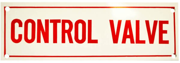
Control valve signage
As detailed in part 3 of this series, control valves control the supply of water to a standpipe system or sections of a standpipe system, and they exist in three areas:
- At the connections to water supplies;
- at areas where portions of the standpipe need to be isolated;
- and at the connections to sprinkler systems.
Control valves are typically only closed for maintenance and testing purposes and must remain open for a system to work in an emergency. Thus, missing signage indicating their location creates significant risk. If a valve is accidentally left closed after testing, for example, firefighters won’t have access to water in the portion of the system that it serves. This is why NFPA’s requirements for control valves are so extensive and include providing detail on which portion of a building is served by a valve, as well as the location of additional valves. Note NFPA 14 code 6.3.8.4, which specifies that a sign must point the way to any control valve in a concealed space or closed room.
Also note 6.3.8.3: When the sprinkler system in a combined standpipe/sprinkler system is fed by more than one standpipe, “a sign shall be located at each dual or multiple feed connection to the combination system” that lets a contractor know of additional control valves for each standpipe that must be closed to isolate the system. The reason for this requirement is practical and simple: testing and maintenance will be compromised or cause damage if all sources of water aren’t shut off, and a contractor should have a clear guide to reopen all valves prior to putting the system back into operation.
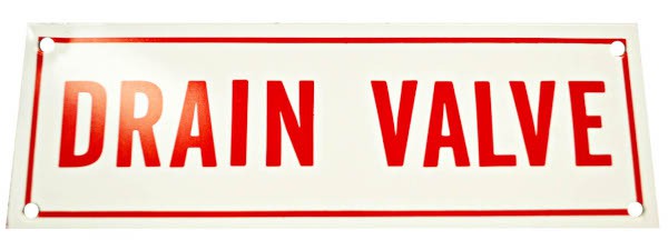
Drain valve signage
A standpipe system should have signs that identify the main drain valve assembly, which serves as the main point to drain water from the system and provides a way to measure water flow during a main drain test. It must also have signs indicating each auxiliary drain that serves the portions of a standpipe system where water may not flow back to the main drain; these are usually necessary at points in the system where the piping changes direction.
Knowing where the system drains is essential for any standpipe that needs to be taken out of service for any period of time, and it is especially important for dry systems that must be drained after use or testing to prevent water from freezing in and damaging the pipes.
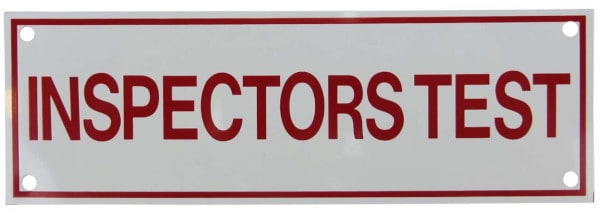
Test connection valve signage
The inspector’s test connection valve can be opened to simulate the flow of water from a single hose connection out of an inspector’s test connection. This valve is used to make sure that the water flow alarm works, to trip test a dry-pipe or pre-action valve in those types of systems, or to simply assess how long it takes for water to arrive to a remote hose connection. The valve should be marked so that it can be easily found to conduct a test, as well as to make sure it is fully closed when not in use.
Hose connection (valve) signage
All hose connections must be identified by a sign, all valve cabinets must have a sign that “indicate[s] the contents,” and NFPA 14 requires special signage (outlined in NFPA 170) to identify “hose connections [that] are not located in exit stairways.” The reason for the last requirement? In addition to mandating enough hose connections so that each one is no more than 120’ to 200’ apart (depending on standpipe class and whether the building is sprinklered), NFPA 14 also requires that all Class I standpipe systems have hose outlets in horizontal exits and exit stairwells. Thus, firefighters default to stairwells when looking for hose connections, and this additional signage helps them find the connections outside of stairwells during an emergency.
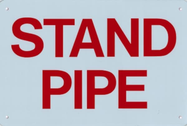
Signage is required at the fire department connection
NFPA 14 requires a sign marking each fire department connection (FDC) and it must indicate whether it is a manual (wet or dry) system, if automatic sprinklers are also supplied by the FDC, whether the FDC services multiple buildings, and “the pressure required at the inlets to deliver the standpipe system demand.”
From the 2016 Edition of NFPA 14
6.4.5.2 Each fire department connection shall be designated by a sign, with letters at least 1 in. (25.4 mm) in height, that reads “STANDPIPE.” For manual systems, the sign shall also indicate that the system is manual and that it is either wet or dry.
6.4.5.2.1 If automatic sprinklers are also supplied by the fire department connection, the sign or combination of signs shall indicate both designated services (e.g., “STANDPIPE AND AUTOSPKR” or “AUTOSPKR AND STANDPIPE”).
6.4.5.2.2 A sign also shall indicate the pressure required at the inlets to deliver the standpipe system demand.
6.4.5.3 Where a fire department connection services multiple buildings, structures, or locations, a sign shall be provided indicating the buildings, structures, or locations served.
Regarding the need to indicate the pressure required to deliver system demand, Professor Kenneth Isman writes that “in [his] experience, this requirement is rarely met. The standard operating procedures of most fire departments are to connect to the FDC and charge it to 150 psi. If the pressure demand at the standpipe is greater than 150 psi, then the fire department might want a sign letting them know that a higher pressure is necessary.”
Thus, while NFPA 14 specifies that the FDC sign must have this information, very few do, and NFPA 25 outlines no inspection requirements for verifying this information is present. Consult with your local authority having jurisdiction to determine the need for this detail.
Signage is required at an onsite fire pump
Automatic and semiautomatic standpipe systems require an onsite fire pump, and it must be identified with a sign that details the minimum pressure and flow required to meet system demand.
From the 2016 Edition of NFPA 14
6.7 Signs for Water Supply Pumps. Where a fire pump is provided, a sign shall be located in the vicinity of the pump indicating the minimum pressure and flow required at the pump discharge flange to meet the system demand.
The pressure requirement for a hydraulically-designed standpipe is “a minimum residual pressure of 100 psi at the most remote 2.-in. [hose] outlet on a Class I system.” The majority of existing standpipes and all new installs are hydraulic systems vs. pipe schedule systems, so this is the rule-of-thumb requirement. It is based on the fact that “most fire departments operate their interior attack handlines with combination nozzles, which are designed to operate at 100 psi residual pressure.”
The flow requirement for a class I standpipe is “500 gpm (gallons per minute) at the most hydraulically remote standpipe through the two most remote outlets.” An additional 250 gpm is added to system demand “at the most hydraulically remote outlet for each additional standpipe in the building” up to a maximum flow of “1,000 gpm for buildings protected throughout with an automatic sprinkler system and 1,250 gpm for buildings that are not.” Note that for a “horizontal standpipe system with three or more connections on any floor the minimum flow rate for the most hydraulically demanding horizontal standpipe is 750 gpm.”
Obviously, an onsite fire pump must be able to meet these demands and not exceed maximum flow and pressure, and the sign must indicate “the minimum pressure and flow required at the pump discharge flange” to fulfill a specific system’s demand. This information is useful when conducting the annual performance testing of the fire pump outlined in Chapter 8 of NFPA 25.
A hydraulic design information sign is required
All standpipe systems must have a sign indicating “the basis of the system design.”
From the 2016 Edition of NFPA 14
6.8.1 The installing contractor shall provide a sign identifying the basis of the system design.
6.8.2 The sign shall be located at the water supply control valve for automatic or semiautomatic standpipe systems and at an approved location for manual systems.
There are two designs for a standpipe system: the older pipe schedule method and hydraulic design. Pipe schedule requires an exact number of sprinklers to be fed off of a specifically-sized pipe at system pressure, whereas hydraulic systems allow the use of a flexible number of hose connections based on a certain area’s hazard classification. NFPA restricts the use of pipe schedule systems for new installations, so the vast majority of systems are hydraulically designed. The signage must indicate which design is used, and hydraulic system signs must list the below information:
From the 2016 Edition of NFPA 14
6.8.3 The sign shall indicate the following:
(1) Location of the two hydraulically most remote hose connections
(2) Design flow rate for the connections identified in 6.8.3(1)
(3) Design residual inlet and outlet pressures for the connections identified in 6.8.3(1)
(4) Design static pressure and the design system demand (i.e., flow and residual pressure) at the system control valve, or at the pump discharge flange where a pump is installed, and at each fire department connection
A final note on standpipe signs
Remember, NFPA 14 demands that all signs are:
- “Permanently marked and shall be constructed of weather-resistant metal or rigid plastic materials” (4.10);
- And “secured to a device or the building wall with corrosion-resistant chains or fasteners.” (6.6)
Keep your standpipe system compliant and safe
Making sure a standpipe system has the appropriate signs doesn’t simply keep it compliant with code – identifying components also helps contractors and building owners conduct tests and avoid liability while enabling firefighters to do their jobs during an emergency. At QRFS, we offer a variety of signs, decals, and stickers to keep your system properly marked.
This concludes our series, The Complete Guide to Standpipe Systems. If you have any questions about standpipes, replacement components, signage, or the tools required to maintain and test your system, give us a call at 888.361.6662 or email us at support@qrfs.com.
Get Standpipe System Signs Here
Check us out on Facebook and Twitter!
Additional Sources:
1. Alpert, Rick. “Standpipe Systems: Design and Installation Requirements.” Sprinkler Age. https://sprinklerage.com/standpipe-systems-design-installation-requirements/
2. NFPA 25: Standard for the Inspection, Testing, and Maintenance of Water-Based Fire Protection Systems (2017)
3. NFPA 14: Standard for the Installation of Standpipe and Hose Systems (2016)
4. Isman, Kenneth E. Standpipe Systems for Fire Protection. Springer International Publishing.
Can you please post a link to a hydraulic design information sign for standpipe (not for sprinkler)? Thanks in advance
Reposting